
repeating interval timer

The adjustable output timer circuit typically employs a combination of resistors, capacitors, and a timer IC, such as the 555 timer, to achieve its functionality. The 555 timer can be configured in either monostable or astable mode, depending on the desired operation.
In monostable mode, the timer produces a single pulse when triggered, with the duration of the pulse determined by the resistor-capacitor (RC) time constant. The output period can be adjusted by changing the values of the resistor and capacitor in the timing circuit. The output can be connected to various loads, such as LEDs, relays, or other electronic devices.
In astable mode, the 555 timer continuously oscillates between high and low states, producing a square wave output. This configuration allows the circuit to re-trigger at regular intervals without external triggering. The frequency of oscillation is determined by the resistors and capacitor connected to the timer, allowing for fine-tuning of the output period.
For longer intervals, additional components such as flip-flops or microcontrollers may be integrated into the design to extend the timing capabilities. These components can provide more precise timing control and the ability to program specific output durations and intervals.
Overall, this adjustable output timer circuit is versatile and can be implemented in various applications, including automation systems, timed lighting, and other scenarios requiring periodic activation of devices. Proper selection and configuration of components are crucial to achieving the desired timing characteristics and reliability of the circuit.This circuit has an adjustable output timer that will re-trigger at regular intervals. The output period can be anything from a fraction of a second to half-an-hour or more - and it can be made to recur at regular intervals of anything from seconds to days and beyond.. 🔗 External reference
Related Circuits
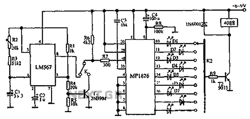
The circuit illustrated in the figure incorporates the MP1826 as a multi-stage divider. The LM567 serves as the frequency demodulation component, functioning as a dual-band oscillator that generates the desired low-frequency pulse from the MP1826. The oscillation center frequency...

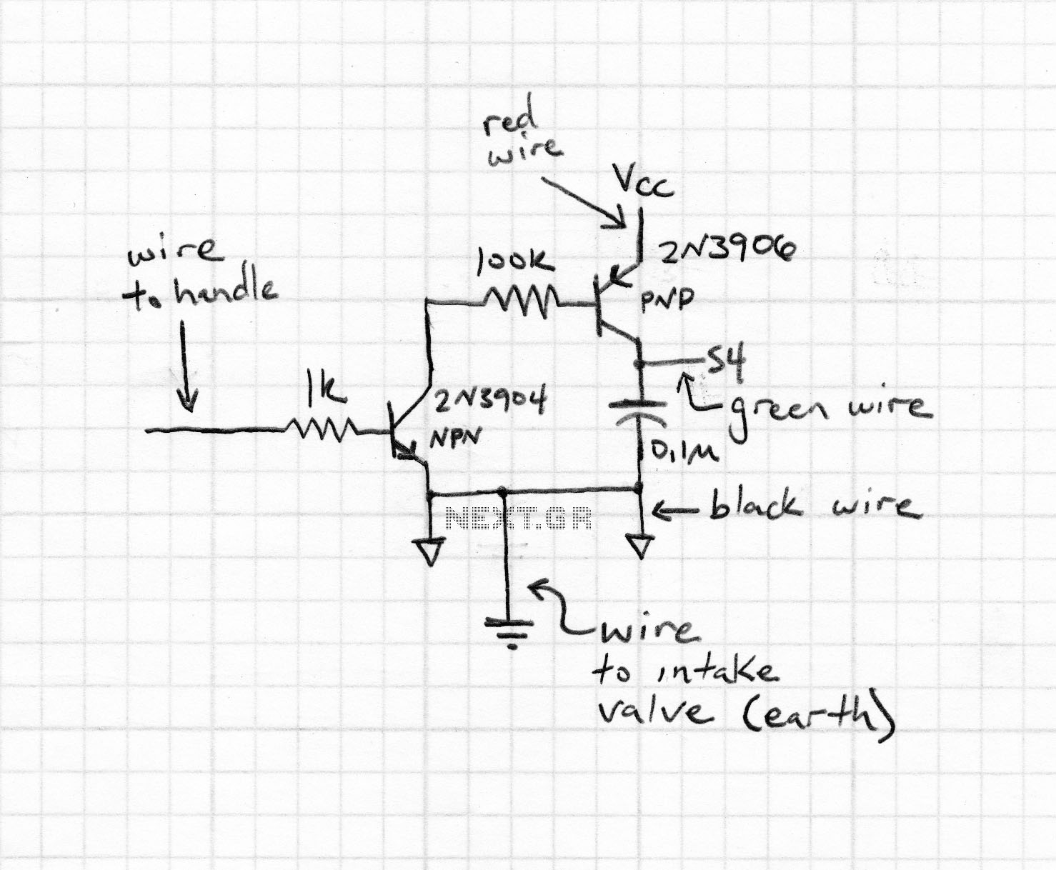
The following method allows the timer to be triggered by a normally closed switch. This would be useful in applications such as intrusion alarms where the protection circuit is broken if a window or door is opened. Trigger Input...
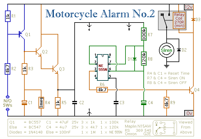
This circuit provides an intermittent siren output with an automatic reset function. It can be manually activated using a key switch or a concealed switch, and it can also be configured to engage automatically when the ignition is turned...
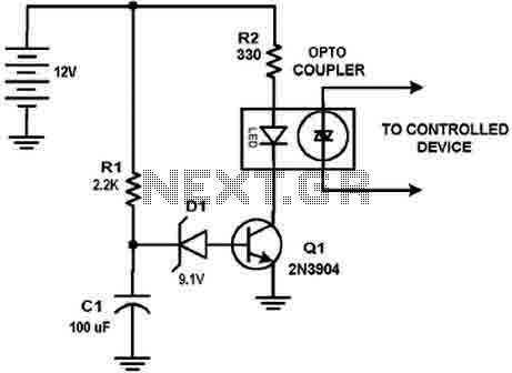
This circuit design was used to switch on device via a LED photocell arrangement (optocoupler) using components R1, C1, D1 and Q1. It produces a delay on powering up to ensure correct sequencing of certain equipment. A very simple...
An intervalometer for the Canon 400D camera has been developed. This device is based on an Arduino platform and utilizes code adapted from the creator of the Intervaluino project. The intervalometer is a specialized electronic device designed to automate the...
This circuit includes a Relay Timer Circuit. One of the most commonly used circuits is that of the 555 Timer integrated circuit (IC). The circuit is designed to control a relay based on a timing interval. The Relay Timer Circuit...