
Schematic Diagram Trigger Input Control Of 555 Timers

The described method utilizes a 555 timer in a monostable configuration, which is ideal for applications requiring a single pulse output upon activation. In this scenario, a normally closed switch is integrated into the circuit. Under normal conditions, the switch remains closed, allowing the circuit to function without interruption. When the switch is opened, as in the case of a door or window being breached, the circuit detects the change in state.
The 555 timer's trigger input (pin 2) is connected to the normally closed switch. When the switch is closed, pin 2 is held high, preventing the timer from triggering. Upon the opening of the switch, pin 2 is momentarily pulled low, which triggers the timer and initiates its timing cycle. The output from pin 3 can then be used to activate an alarm or other alerting mechanism.
To ensure reliable operation, it is important to include a pull-up resistor connected to the supply voltage at pin 2. This resistor ensures that pin 2 remains high when the switch is closed. Additionally, a capacitor can be connected between pin 6 and ground to set the duration of the output pulse, while a resistor between pin 7 and the supply voltage determines the timing interval.
This configuration is particularly advantageous for security applications, as it allows for immediate detection of unauthorized access, providing a prompt response to potential intrusions. The simplicity and reliability of the 555 timer make it an excellent choice for such control circuits.The following method allows the timer to be triggered by a normally closed switch. This would be useful in applications such as intrusion alarms where the protection circuit is broken if a window or door is opened Trigger Input Control Of 555 Timers 🔗 External reference
Related Circuits
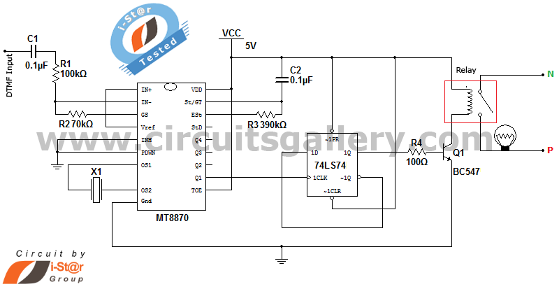
It is possible to control home and office electrical appliances using a mobile phone. This document presents a simple home automation electronic mini project circuit diagram designed for engineering students, allowing the control of electrical appliances without the use...
A very regular configuration of the 555 astable timer to work as a timer to trigger an alarm or any other equipment connected to pin 3. R resistor should be replaced with a potentiometer that will change the time...
The simple pressure sensor alarm is constructed using a few inexpensive and readily available components. The operation of this circuit is straightforward and self-explanatory. When powered by a 9V compact battery, the active piezo sounder at the output of...
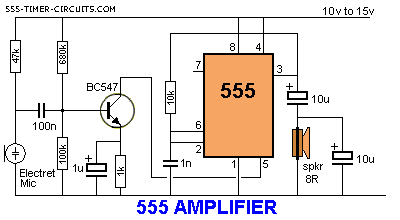
The 555 timer can function as an amplifier, operating similarly to pulse-width modulation. The component values lead the 555 to oscillate at approximately 66 kHz, a frequency to which the speaker does not respond. Instead, the speaker reacts to...
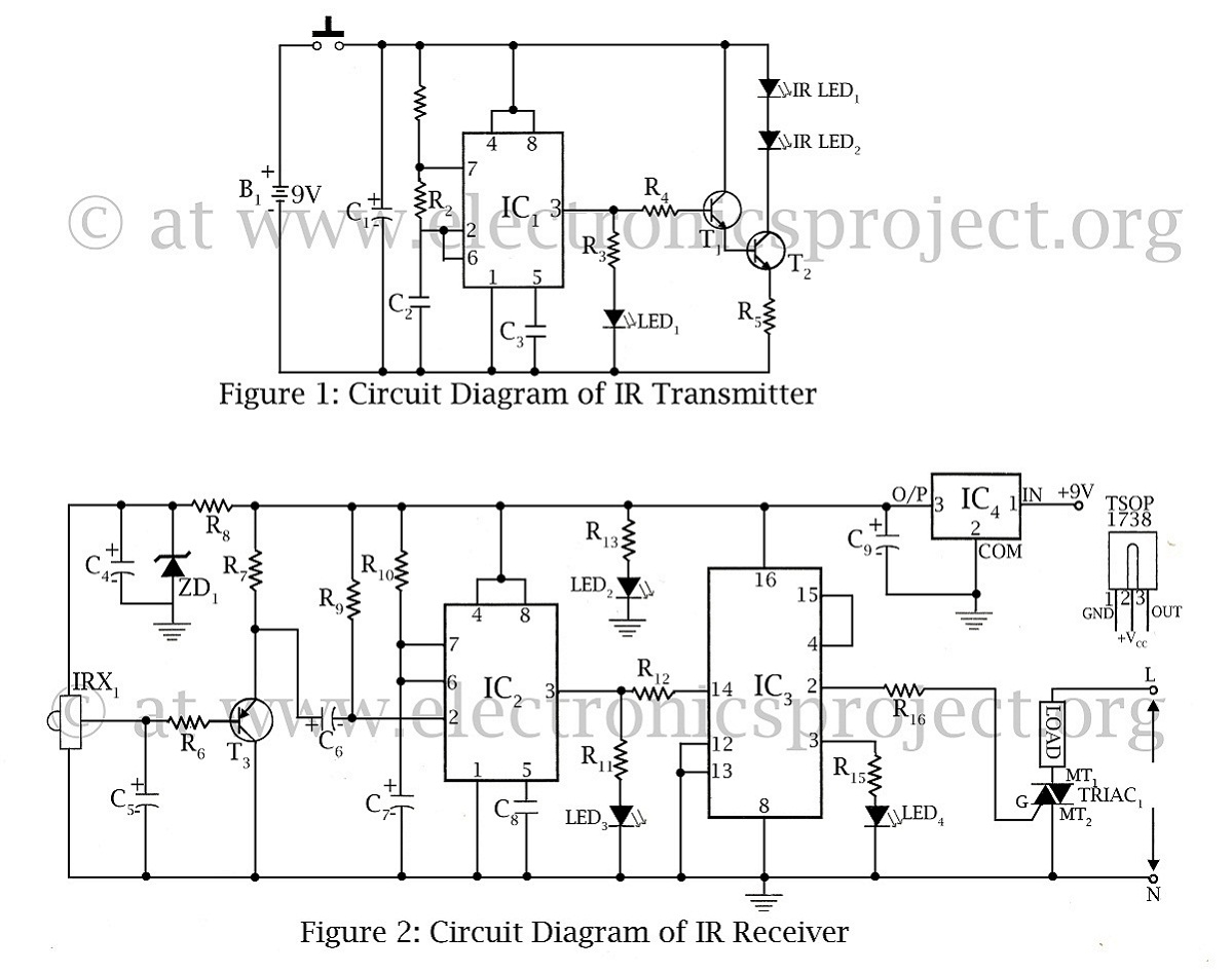
The infrared remote-controlled switch is the second remote-controlled project on this website, utilizing a 555 IC circuit diagram along with a description of the remote-controlled switch. The infrared remote-controlled switch operates using a 555 timer integrated circuit (IC), which is...
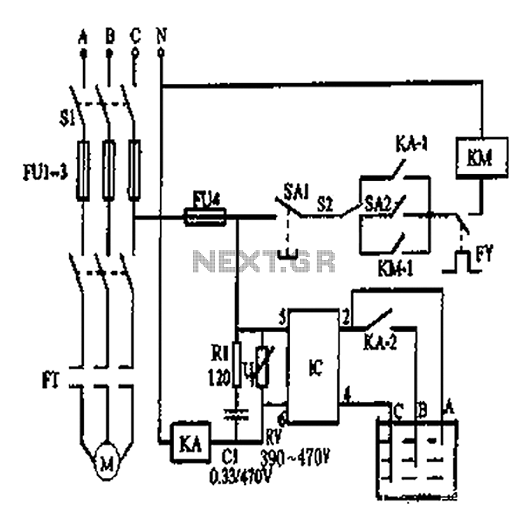
An automatic water tank system is illustrated in the circuit diagram. The circuit employs a PSSR AC solid-state relay, which is a new type of solid-state relay designed for AC applications. Unlike traditional solid-state relays (SSR), this PSSR not...
Warning: include(partials/cookie-banner.php): Failed to open stream: Permission denied in /var/www/html/nextgr/view-circuit.php on line 713
Warning: include(): Failed opening 'partials/cookie-banner.php' for inclusion (include_path='.:/usr/share/php') in /var/www/html/nextgr/view-circuit.php on line 713