
Replacing Motorola Batteries
The described battery replacement and charging circuit modifications are critical for enhancing the performance and longevity of the radio device. The implementation of a homebrew battery pack using NiMH cells significantly increases the capacity, allowing for extended use between charges. The approach involves careful assembly of the battery pack with attention to the orientation and connections of the terminals, ensuring reliable contact points for the charger. The addition of the blocking diode is crucial in preventing reverse current flow, which could damage the battery or the device.
To facilitate the charging process, the modifications to the charger circuitry involve specific resistor adjustments that directly impact the current flowing to the batteries. By replacing R2 and R5 with a lower resistance value, the charging current is increased, thereby reducing the total charging time and improving efficiency. This change is particularly beneficial in applications requiring frequent battery replacements, as it allows for quicker turnaround times while maintaining safety standards.
In summary, the combination of a homemade battery pack and optimized charging circuitry provides a practical solution for extending the operational life of the radio device, demonstrating effective engineering practices in battery management and circuit design.These were about $60 a pair with charger and batteries, and have a three-bar battery gauge. With experimentation I found that if the voltage is greater than 4. 28V, all three bars light up. More than 3. 47V, two bars will light up. Below this latter voltage the radio chirps regularly, and only one bar will light up. After a few years use, we noticed the batteries do not last longer than a few hours, so I wanted to replace them. A search on the web shows that the battery packs are about $12 each (plus shipping), and their capacity is still only 600mAh, so I decided to investigate a home-brew battery replacement for these units. I pealed back the sticker on one battery pack and discovered that the hidden elecronics are very simple and can be easily reproduced.
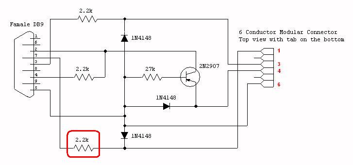
One terminal of the charger connections connects to the negative terminal of the battery pack, and the other terminal connects to the positive terminal via a blocking diode. Insert the three batteries into the radio, and verify that it powers up. If it doesn`t you may have to bend the metal tabs out to meet the battery terminals. Remove the paper backing, on the tape, and fold the tab over so that the tape forms a `b` shape. The top arm of the `b` is not sticky on either side because you folded the tab over. The bottom belly of the `b` is sticky. Tape the bottom (belly) part of the `b` onto a corner of the paper substrate (top copper tab in the pictures below).
Have the non-sticky top arm stick out of the edge. Insert the top arm of the `b` under the negative terminal of the battery. Since you folded the tab under, both sides of this leg are exposed copper and will make good contact with the battery and the radio terminal. Tape the 0. 75" square piece of copper tape in the opposite corner of the paper (see below). The two previous squares now form the charging contacts for the new pack. Insert the leg of this `P` under the positive terminal of the right most battery (not sticky), and glue the exposed tape onto the paper substrate (bottom picture).
Solder the diode to the latter two copper tabs. Cathode ring toward the positive battery terminal as shown in the bottom picture. Put the diode in the crease formed by the gap between the two batteries. The original battery packs are only 600mAh units. The new ones are more than three times the capacity (I used NiMH), and should last us a few days between recharging with even daily use. Remember to recycle your used batteries as they contain Cadmium. After some use it became clear that the circuitry in the charger needed to be modified to provide more charge current for the batteries.
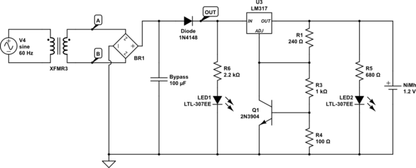
Tracing the circuit, I came up with this schematic. To increase the charging current, I shorted R3 and R6 with a jumper and replaced R2 and R5 with a 10 Ohm resistor. This quadruples the charging current from the standard 39mA to 155mA (both measured). It is still below the C/10 slow charge rate, so it should be safe to leave the radios charging for extended periods.
🔗 External reference
Related Circuits
This battery charger is designed for charging sealed lead-acid batteries using a solar panel in portable applications such as baby carriages. The standard diode that prevents the current from flowing back through the solar panel has been replaced with...
This article provides an overview of the R100 and MCR100 UHF repeaters. All information was obtained from a physical examination of the station, the programming software, and the R100 Instruction (and service) Manual, p/n 6881078E15, as well as the...
An Arduino powered by 2 or 4 rechargeable NiMH AA batteries is being developed. The choice of using two batteries is based on the intention to boost the voltage to meet the requirements. The main challenge is ensuring that...
A new type of NiMH battery known as HeCell has recently been developed, which is claimed to allow higher discharge rates than the conventional ones (about 12 - 16C). The HeCell NiMH battery represents a significant advancement in battery...
This circuit was designed for digital cameras, which are known to have significant power consumption. For instance, the Minolta E223 camera requires approximately 800 mA. In practice, this demand can be met using a mains power supply or high-capacity...
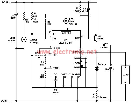
The MAX712 charger requires a power supply with an output voltage that is at least 1.5V higher than the maximum battery voltage. Charge completion is determined by a voltage-slope detecting analog-to-digital converter, a timer, and a temperature window comparator. The...