
Batteries charger & PSU - ideal for digital camerass
The described circuit for digital cameras integrates a charger and an adapter, effectively addressing the power requirements of devices with high consumption rates. The adapter utilizes an LM317 adjustable voltage regulator, which is versatile for various camera models. The output voltage range of 2-9 V is particularly beneficial, allowing compatibility with different camera power specifications.
The charger section employs a 7805 voltage regulator, ensuring a stable output that is essential for safe battery charging. The inclusion of a potentiometer allows for fine-tuning of the charging current, which is critical for battery health and longevity. The ability to charge multiple batteries simultaneously enhances the circuit's utility, making it suitable for users with multiple battery packs.
The mechanical mains timer adds a layer of functionality, allowing users to set charging durations based on manufacturer recommendations. This feature compensates for the lack of automated charging time measurement in the circuit, ensuring that batteries are charged adequately without the risk of overcharging.
Overall, the circuit is designed with practicality in mind, offering a straightforward solution for powering and charging digital cameras while accommodating various battery configurations. The components selected for this design are commonly available, making the circuit accessible for hobbyists and professionals alike.This circuit was created for digital cameras. It`s known the digital cameras have considerable power consumption. For example my camera Minolta E223 requires approximately 800 mA. In practice a mains power supply or high capacity NiMH accumulators (batteries) can satisfy this demand. This circuit consists of two parts, charger and adapter. The tra nsformer, rectifier bridge and buffer condensator are common. Adapter is quite simply its main part is an adjustable voltage regulator LM 317 according to usual setting. Output is a suitable for camera jack plug. Voltage can be adjusted in range 2-9 V. In the charger circuit a 7805 fixed voltage regulator works as current generator assured constant current during charging.
This charging current can be adjusted with the 100 /1W potentiometer in range about 50-300 mA indicated by a small current measuring instrument. From one to four batteries can be charged simultaneously. The switch must be set according to number of batteries, and charging current of batteries given by manufacturer must be adjusted.
This circuit doesn`t measure charging time and charging condition of batteries. Manufacturers give charging time, usually 14-16 h. I solved this problem with a simply, cheap mechanical mains timer. I think its accuracy is sufficient. 🔗 External reference
Related Circuits
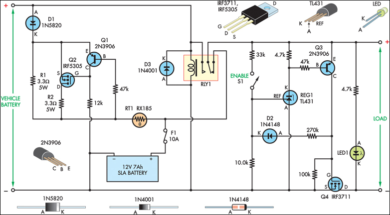
The SLA battery is charged from the vehicle's battery. When the engine is running, the voltage remains fairly constant, which greatly simplifies the charging circuit. If the SLA battery is fully charged, any further charging current from the vehicle...
The input mentions the 89S51/52 microcontrollers, but the accompanying image shows the 89C51. Clarification is needed regarding which microcontroller should be used with the provided .hex file without requiring changes to the file. The 89S51 and 89S52 are part of...
Analog-to-digital converters (ADCs), printed-circuit board (PCB), microcontroller or digital signal processor (DSP), total-harmonic-distortion (THD), signal-to-noise ratio (SNR). Analog-to-digital converters (ADCs) are essential components in modern electronic systems, enabling the conversion of analog signals into digital form for processing by microcontrollers...
By utilizing a reverse binary counter along with a binary-coded decimal (BCD) decoder, a step voltage can be generated, which can then be approximated to produce a sine wave signal with adequate accuracy for various applications. In the digital...
This is the second instructable focused on creating a digital watch as a learning experience. An Atmega644 chip from a Sanguino was available, which would have sufficed, but the intention was to burn an Arduino bootloader and test its...
Normally, an analog-to-digital converter (ADC) requires interfacing with a microprocessor to convert analog data into digital format. This involves additional hardware and software, leading to increased complexity and overall cost. The circuit of the A-to-D converter presented here is...