
Resistive neutral leakage protection circuit
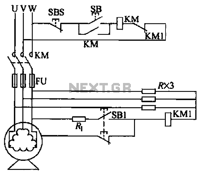
The described voltage leakage protection circuit serves a critical function in safeguarding electrical systems from potential faults that could lead to dangerous leakage currents. The circuit employs a resistive element strategically placed to create an auxiliary neutral point, which helps in monitoring and managing voltage levels effectively.
In this configuration, the resistive element is selected based on its resistance value, which must align with the specific application requirements to ensure optimal performance. The power rating of the resistor is equally important, as it must be capable of dissipating the heat generated during operation without exceeding its thermal limits. This consideration is crucial to maintaining the reliability and longevity of the circuit.
The auxiliary neutral point created by the resistive element allows for the detection of any voltage discrepancies that may arise due to leakage currents. By monitoring the voltage at this point, the circuit can activate protective measures, such as disconnecting the load or triggering an alarm, thereby preventing potential hazards.
In summary, the resistive element in the voltage leakage protection circuit plays a vital role in enhancing the safety and reliability of electrical systems. Proper selection of resistance and power rating is fundamental to ensure the circuit functions as intended and provides effective protection against voltage leakage. By resistive element as an auxiliary neutral point voltage leakage protection circuit, as shown in FIG. Resistance selection should consider the resistance, power consistency r ate.
Related Circuits
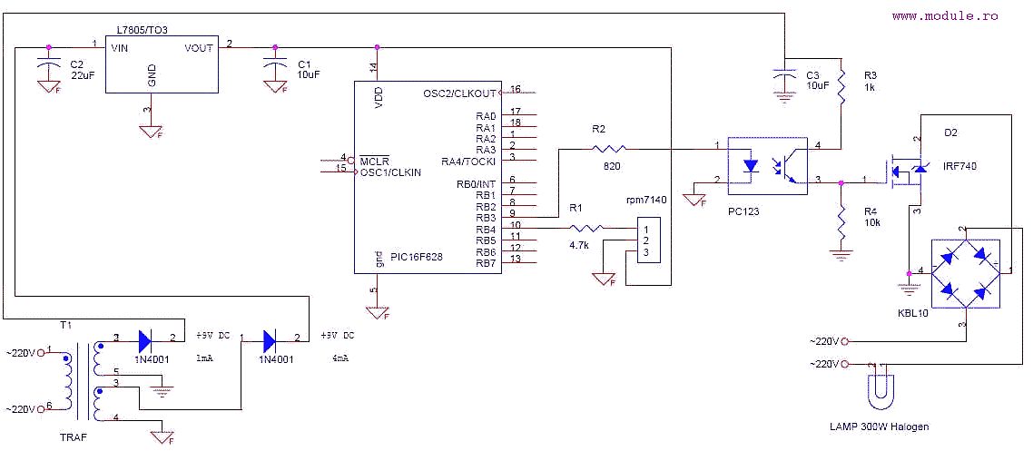
This is a simple schematic designed to control a lamp using a Sony TV remote control. The circuit employs a PWM signal connected to a photocoupler, which isolates the power section from the microcontroller. The power section features an...
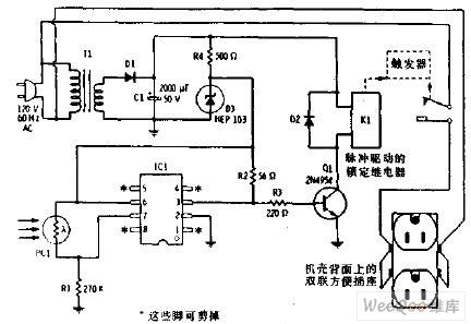
The flash beam can be utilized to power remote control devices for AC power applications. A key feature of this device is its memory function, which allows it to supply power continuously. Upon the second activation, the power will...

The use of a differential capacitor enables temperature compensation in an LC circuit utilizing an NFO and N1500 ceramic. C6 serves as a differential capacitor featuring two stators and one common rotor. When one stator's capacitance reaches its maximum...
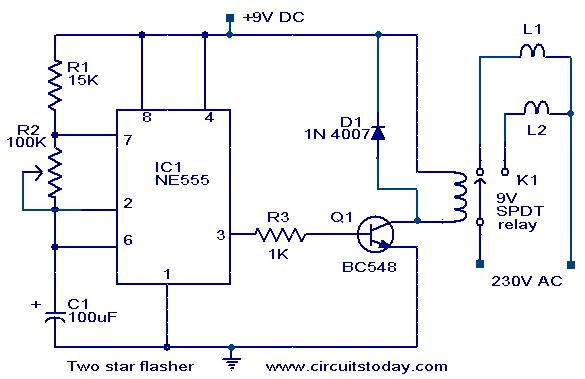
A circuit designed to alternately flash two Christmas stars is presented. The NE555 integrated circuit (IC1) is configured as an astable multivibrator. When IC1 outputs a positive pulse, transistor Q1 becomes conductive, activating relay K1. Consequently, lamp L2, connected...
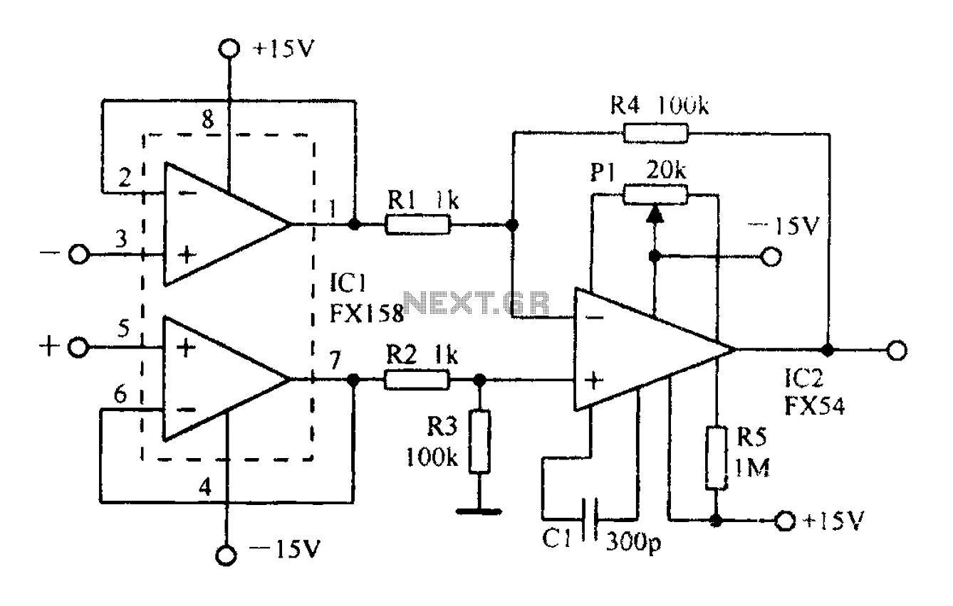
A differential amplifier with input impedance as indicated in the circuit diagram. A differential amplifier is a crucial component in various electronic applications, primarily used to amplify the difference between two input voltages while rejecting any common-mode signals. This characteristic...
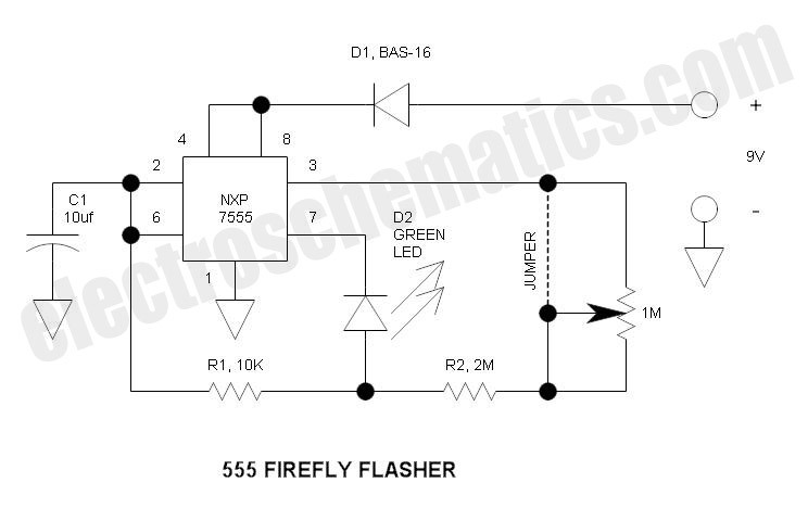
This circuit operates similarly to a standard 555 astable timer, with the distinction that the LED is integrated into the capacitor reset path. Consequently, when pin 7 discharges capacitor C1 to ground, a relatively high current flows through the...
Warning: include(partials/cookie-banner.php): Failed to open stream: Permission denied in /var/www/html/nextgr/view-circuit.php on line 713
Warning: include(): Failed opening 'partials/cookie-banner.php' for inclusion (include_path='.:/usr/share/php') in /var/www/html/nextgr/view-circuit.php on line 713