
A differential amplifier having input impedance equal to the circuit diagram

A differential amplifier is a crucial component in various electronic applications, primarily used to amplify the difference between two input voltages while rejecting any common-mode signals. This characteristic makes it particularly valuable in instrumentation, audio processing, and operational amplifier circuits.
The input impedance of a differential amplifier is a significant parameter, as it affects how the amplifier interacts with preceding stages in a circuit. High input impedance is typically desired to minimize the loading effect on the signal source. In many designs, the input impedance can be influenced by the configuration of the amplifier and the components used, such as resistors and transistors.
In a typical differential amplifier circuit, two inputs are provided, often labeled as V1 and V2. The output voltage (Vout) is proportional to the difference between these two input voltages, expressed mathematically as Vout = A(V1 - V2), where A is the gain of the amplifier. The design may include feedback mechanisms to stabilize the gain and improve linearity.
The circuit diagram for a differential amplifier often includes resistors that set the gain and determine the input impedance. For instance, using high-value resistors at the inputs can increase the input impedance, while ensuring that the amplifier maintains its performance characteristics. Additionally, the choice of transistors or operational amplifiers can also play a critical role in defining the input and output impedances.
In summary, the differential amplifier is an essential building block in modern electronics, with its performance heavily reliant on its configuration, component selection, and input impedance characteristics as depicted in the circuit diagram. Understanding these parameters is vital for optimizing the amplifier for specific applications.A differential amplifier having input impedance equal to the circuit diagram:
Related Circuits
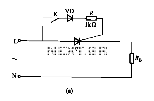
The thyristor AC switch circuit is not triggered, due to its simplicity, cost-effectiveness, and non-contact operation, making it widely utilized. The circuit is illustrated in Figure 16-43. It consists of single-phase thyristor switching circuits. Figure 16-43 (a) depicts a...
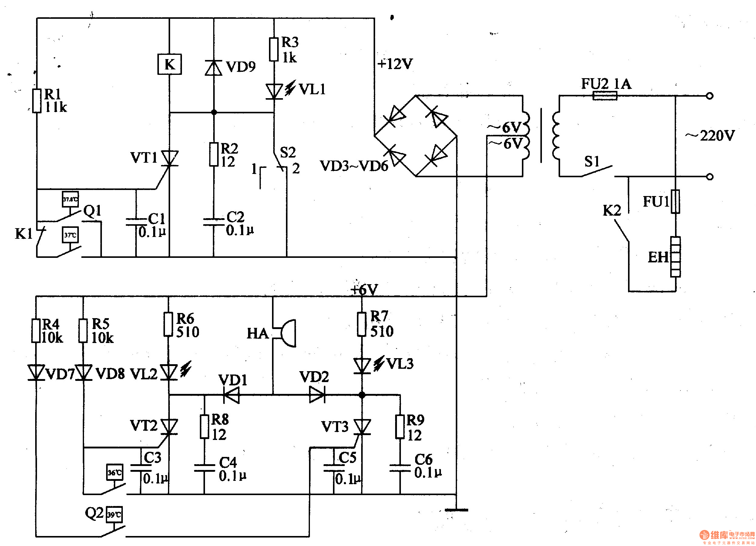
The egg hatching incubator circuit comprises a power supply circuit, a constant temperature control circuit, and a sound and light alarm circuit, as illustrated in Figure 4-7. The power supply circuit includes a power switch (S1), a fuse (FU2),...
This circuit utilizes a photoelectric coupler to achieve 100GΩ isolation between a TTL (Transistor-Transistor Logic) circuit and a relay circuit. This configuration effectively prevents relay noise and peak voltage from affecting the TTL circuit. When the TTL input signal...

The versatile circuit can be employed to achieve various functions, including an astable multivibrator, a monostable multivibrator, a switch debouncer, or a frequency discriminator. Inverters U1a and U1b are configured as a latch. When the input voltage (VIN) is...
This circuit includes a 220µF capacitor and two diodes designed to slow down the switch-on process, thereby minimizing the output thump that occurs as the output capacitor charges through the speaker. While this feature is not essential and may...
A small delay circuit is required to produce a pulse for a cell phone vibrational motor every 0.75 seconds, with an adjustable delay time ranging from 4 to 10 seconds. The circuit will be powered by a 9-volt battery. To...