
Firefly Lights Circuit

This circuit design utilizes the 555 timer in astable mode, where it generates a continuous square wave output. The integration of the LED into the capacitor reset path enhances the visual output while maintaining low power consumption. The LED will illuminate as the capacitor discharges, creating a flickering effect akin to fireflies. The average current draw of around 100 µA ensures prolonged operation even under low battery conditions, making this circuit suitable for applications where battery life is critical.
The use of resistor R2 plays a vital role in the discharge process of capacitor C1. When the voltage across C1 reaches the lower threshold, R2 assists in discharging the capacitor quickly, ensuring that the LED continues to flash until the battery voltage is critically low. The inclusion of diode D1 is essential for protecting the circuit from potential damage due to reverse polarity connections, which can occur during battery replacement or installation.
The aesthetic appeal of this circuit can be enhanced by arranging multiple units to simulate the natural behavior of fireflies. The random flashing of the LEDs adds to the realism, while the larger size of the LEDs compared to actual fireflies allows for easier visibility in various environments. The design can also be tailored by adjusting component values to modify the flashing rate and brightness of the LEDs, providing flexibility for different applications.
Overall, this circuit combines functionality with an engaging visual display, making it a unique project for hobbyists and professionals alike. The simple yet effective design principles of the 555 timer, combined with thoughtful component selection, result in a reliable and visually appealing circuit that can operate under challenging conditions.It functions like almost any 555 astable timer, except that the LED is inserted into the capacitor reset path so that when pin 7 discharges C1 to common, this relatively high current must pass through the LED. In this way, the average battery current is only about 100uA. When battery voltage becomes very low, the LED threshold voltage prevents dis charging C1 down to the lower threshold ”when this happens, R2 finishes off the discharge because the output switches to ground potential the same time pin 7 turns on ”you will find that this works on almost dead batteries that may be useless for other applications. D1 protects against accidental reverse battery voltage. Fireflies are common through Northeastern US and also in many other parts of the world. This green LED has the same color, flashes at about the same duration and has a similar repetition rate just like a real firefly (lightning bug).
Put a number or these around your grounds and they will truly resemble fireflies ”there will be no synchronization of the flashes. The only thing this cannot do is to fly ”fireflies ascend as they flash, and they do not flash when perched to protect from predators.
Also, this is much larger than the tiny firefly beetle that measures about 3 x 20mm. Visible on the photo is a wire jumper connecting R2 to IC pin 3. This was an afterthought when I found that low voltage operation was poor. The PCB file is updated to fix this. The optional resistor is not used in this case, but is easy to add if desired. You may adjust component values to obtain desired results. 🔗 External reference
Related Circuits

The DAC0832 is a digital-to-analog converter (DAC) chip designed for integration with computer bus systems. It features an 8-bit resolution and operates with a single power supply ranging from 5 to 15 volts. The device is compatible with TTL...

This document describes a series of touch switches that utilize only three transistors. These touch-based transistor switches can activate a load simply by the user touching a metal plate. They are designed to directly switch a relay, enabling operation...
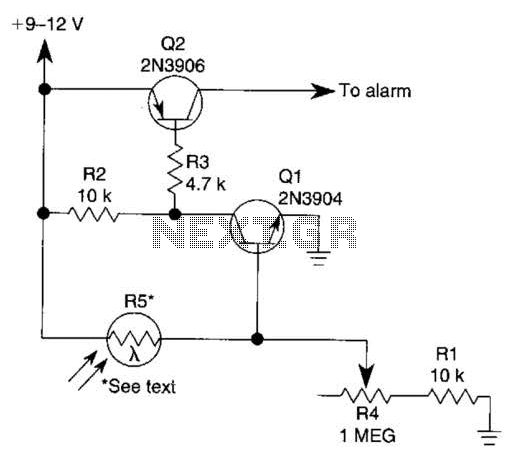
The circuit functions as a sensor capable of triggering an alarm without direct contact from an intruder. It utilizes a visible or invisible light source that illuminates the sensor, maintaining the detection loop in a normally closed state. As...
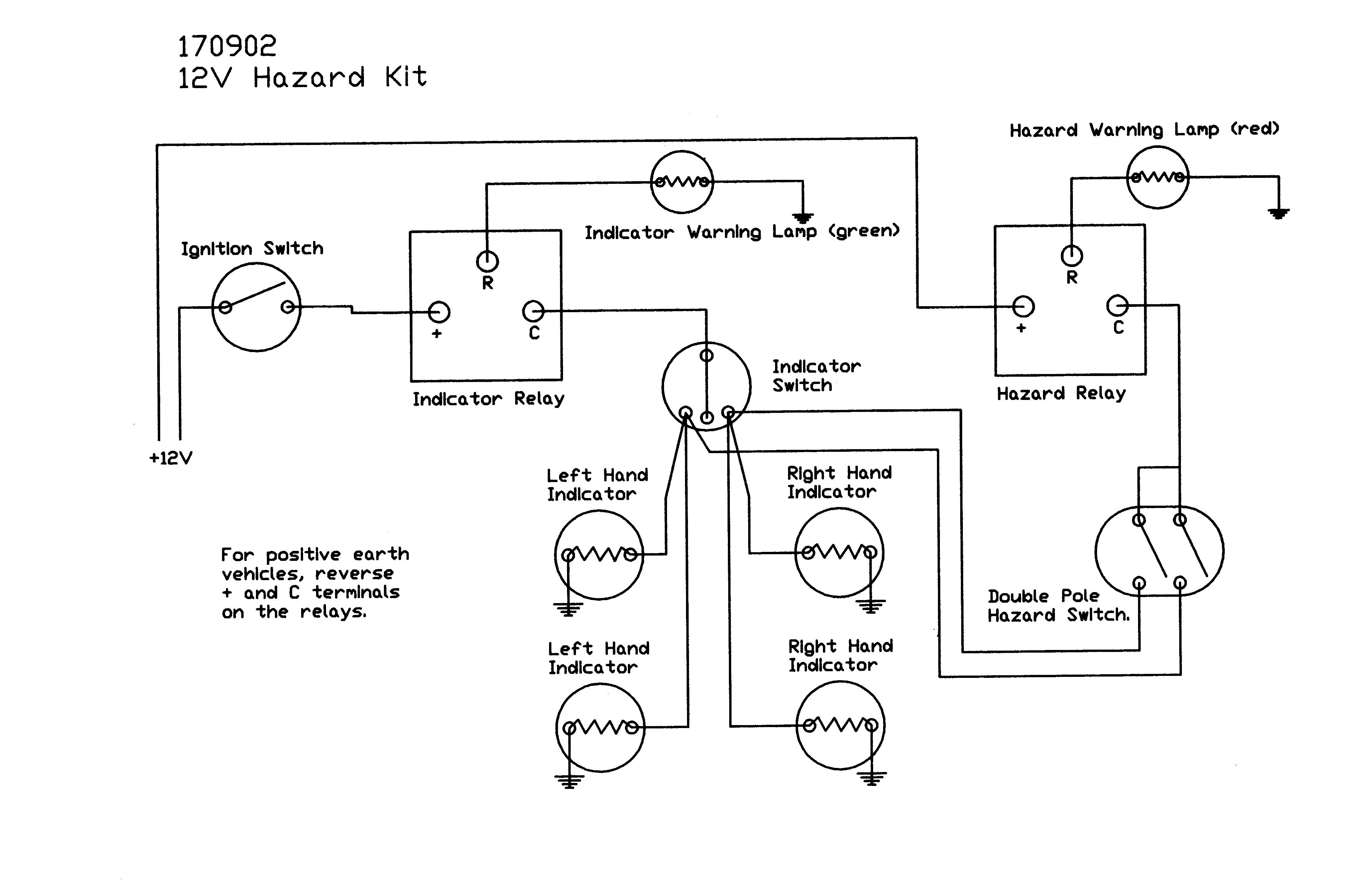
This diagram provides a basic understanding of the system's operation. The only point where the left and right indicators converge from the indicator switch is between the stalk and the hazard switch. It is advisable to remove the steering...
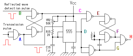
The alarm detector circuit operates differently from the Ultrasonic Alarm (1). In Ultrasonic Alarm (1), an alarm output is triggered by the detection of a reflected wave from an object during the setup time. Conversely, in this circuit, an...

The circuit is depicted in Figure 1, while the electrical schematic diagram is presented in Figure 2. The AC voltage of 220V is reduced by components C3 and R3. The diodes VD1 and VD2 rectify the voltage, and capacitors...
Warning: include(partials/cookie-banner.php): Failed to open stream: Permission denied in /var/www/html/nextgr/view-circuit.php on line 713
Warning: include(): Failed opening 'partials/cookie-banner.php' for inclusion (include_path='.:/usr/share/php') in /var/www/html/nextgr/view-circuit.php on line 713