
resistors About a homemade SLA battery charger
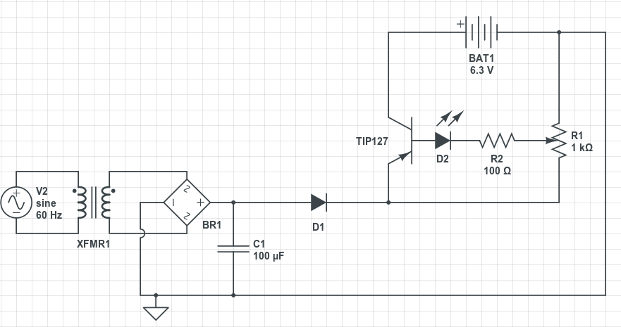
The circuit is designed to demonstrate fundamental electronic principles through a straightforward assembly of passive and active components. The choice of components, such as resistors and capacitors, allows for the exploration of basic concepts like voltage division, filtering, and time constants in RC circuits. Transistors will be employed to illustrate their role in signal amplification and switching functions.
For instance, a basic RC low-pass filter can be constructed using a resistor and capacitor in series, with the output taken across the capacitor. This configuration allows for the examination of how the circuit responds to different frequencies, providing insights into the behavior of reactive components. The cutoff frequency can be calculated using the formula f_c = 1 / (2πRC), where R is the resistance and C is the capacitance.
In addition, a simple transistor amplifier can be created using a common-emitter configuration. This setup will involve connecting a transistor with appropriate biasing resistors to ensure it operates in the active region. The input signal can be fed through a coupling capacitor to block any DC offset, while the output can be taken across the load resistor connected to the collector. This arrangement will allow for the analysis of gain and input/output characteristics.
By limiting the construction to available components, the circuit not only serves its educational purpose but also encourages resourcefulness and creativity in circuit design. Overall, this project aims to provide a practical understanding of basic electronic components and their interactions in simple circuits.The circuit has educational purpose, so being simple is a must. I`m also trying to build it only with components that I already have (a bunch of resistors, capacitors, transistors and none IC). 🔗 External reference
Related Circuits
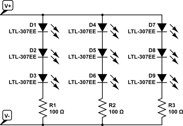
The project involves installing LED strips in a car's tail lamps to replace conventional bulbs. The required lengths for the LED strips are 16 inches, 15 inches, and 14 inches to fit properly within the housings. The selected LED...
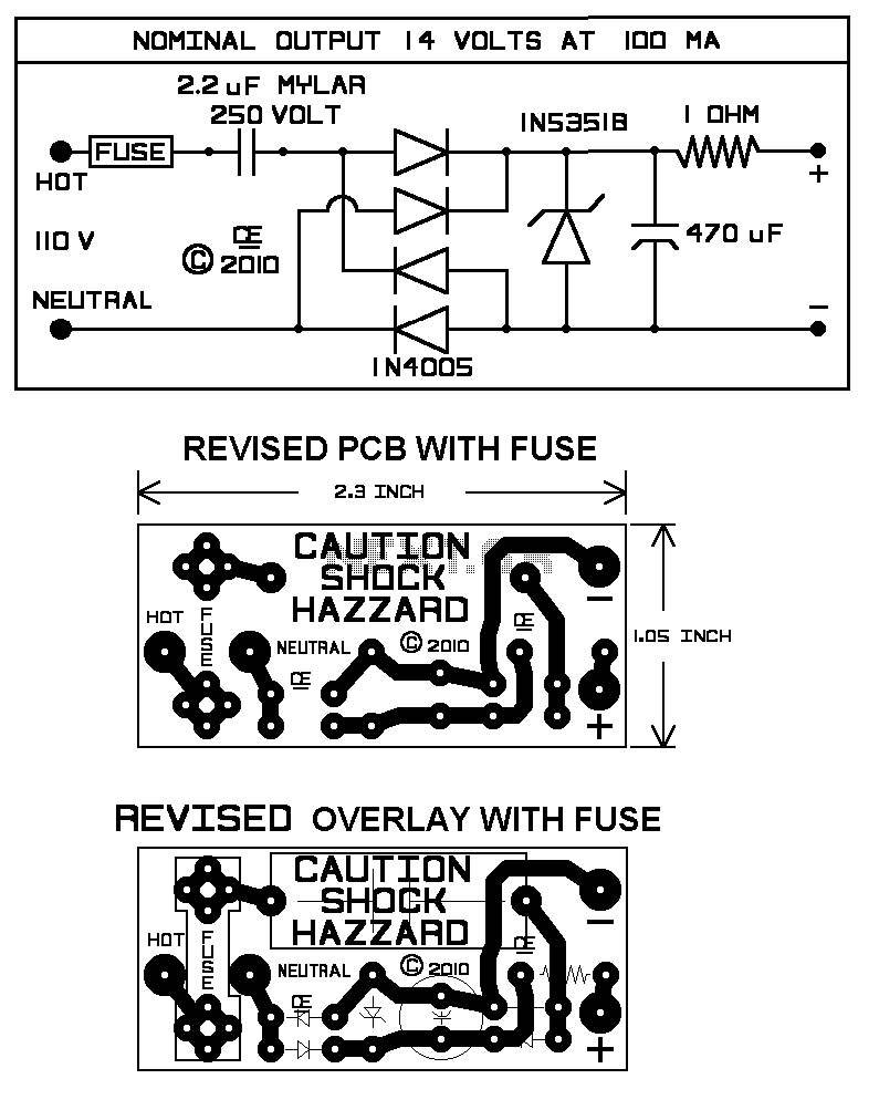
Using this circuit will give good charging results to a sealed lead acid battery, like I use in the metal detector. This circuit is extremely small in size and has a low parts count, making it ideal in some...
This article describes three options for interfacing the DS1859 to the MAX3735. It includes a new technique using an operational amplifier that provides a linear transfer function, which can be adjusted for any arbitrary current range. All of these...
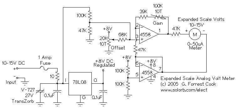
This circuit is used to measure the voltage on a 12V (nominal) lead acid rechargeable battery system. It was specifically designed for use in solar powered systems, but is general enough that it can be used for automotive or...
Due to the high voltages present in the Charge and Primary sections, it is logical to seek cables with high voltage ratings, such as neon sign cables, medical X-ray equipment cables, and car engine spark plug leads. The first...
To charge lead-acid batteries, a circuit can be utilized that consists of a current-limited power supply and a flyback converter topology. The described circuit for charging lead-acid batteries employs a current-limited power supply in conjunction with a flyback converter...