
Lead Acid Battery Charger Circuit
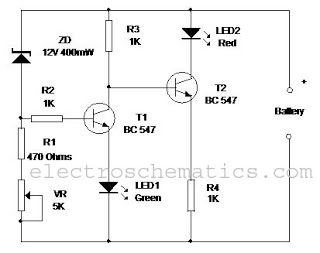
The described circuit for charging lead-acid batteries employs a current-limited power supply in conjunction with a flyback converter configuration. This design is effective in ensuring that the batteries receive the appropriate charging current without exceeding their maximum ratings, thus preventing damage and prolonging battery life.
The current-limited power supply is essential for regulating the voltage and current supplied to the battery. It typically includes a transformer, rectifier, and filtering components to convert the AC input into a stable DC output. The flyback converter topology is particularly advantageous in this application due to its ability to provide electrical isolation between the input and output while also allowing for efficient energy transfer.
In the flyback converter, energy is stored in the magnetic field of the transformer during the on-time of the switching device (usually a MOSFET). When the switch is turned off, the stored energy is released to the output through a diode, which rectifies the voltage for charging the battery. This method allows for high efficiency and compact design, making it suitable for applications where space is limited.
The circuit may also incorporate additional features such as over-voltage protection, temperature compensation, and status indicators to enhance functionality and safety. Overall, this charging circuit design is an effective solution for maintaining lead-acid batteries in optimal condition.To charge lead-acid batteries we can use this circuit that consist of a current-limited power supply and a flyback converter topology. Here is the schematic.. 🔗 External reference
Related Circuits
This circuit monitors the charging process of a 12 Volt Lead Acid or Tubular battery. The LED status indicates whether the battery is charging and signals when it reaches a full charge. It can be integrated into various battery...
The following circuit illustrates a 2500W Phase Control Circuit Schematic. Features include a ground-tied trigger output that is disabled, and a low voltage input. The 2500W Phase Control Circuit is designed to regulate the power delivered to a load by...
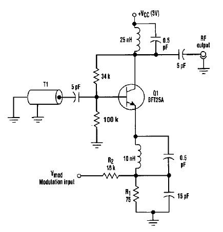
This varactorless high-frequency modulator electronic project must be powered by a simple DC 3-volt power source, such as a 3-volt battery. Traditionally, high-frequency oscillators are frequency-modulated using a varactor. However, varactors typically require a significant voltage change to achieve...
The electric car remote control circuit diagram enables the model car to move forward and backward, as well as turn left and right. It is simple and easy to operate. The radio remote control receiver demodulation circuit utilizes TWH9238...
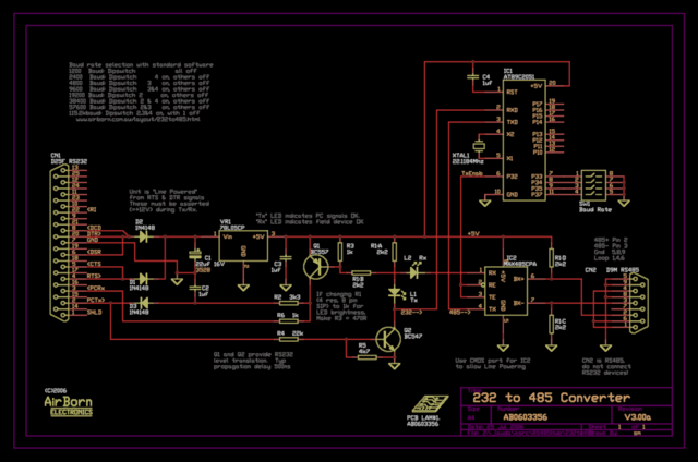
The new version of the RS485 interface addresses the issues associated with RTS control, which was a challenge in the previous design. However, implementing this solution requires a microprocessor, adding complexity to the design. This unit is currently being...
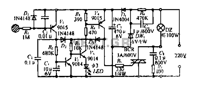
Diagram 2 depicts a shake tube circuit with a capacitance (C) and a trigger voltage rectifier filter element. The circuit includes a trigger voltage transistor amplifier (H), three pull tubes (n, U, v), and utilizes a thyristor as a...