
Resonance generators by 4011 CMOS Gate

This circuit employs a CMOS 4011 integrated circuit, which contains four NAND gates that can be configured to create two separate oscillator circuits. Each oscillator circuit is composed of two NAND gates. The configuration allows for the generation of two distinct frequency ranges: one higher frequency range utilizing IC1c and IC1d, and a lower frequency range utilizing IC1a and IC1b.
The operation of the circuit is initiated by generating a low-frequency pulse, which serves to control the functioning of the oscillators. Diode D1 is strategically placed to manage the output from IC1c and IC1d, ensuring that the low-frequency pulse is directed appropriately. In contrast, diode D2 is critical for producing the oscillating sound, effectively converting the electrical signals into audible sound waves.
The inclusion of switch S1 provides user control over the oscillation speed, allowing for gradual adjustments. This feature is particularly useful in applications where varying sound frequencies are required. The discharge characteristics of capacitor C1 are not stringent, meaning that it can function effectively without needing to be of a highly precise value. This flexibility simplifies the circuit design and component selection process.
The output sound is delivered through a speaker (SP1), which should be a crystal transducer. This type of transducer is chosen for its ability to accurately reproduce the sound generated by the oscillations, making it suitable for applications in sound generation and signal processing. Overall, the circuit offers a versatile solution for generating oscillating sounds across different frequency ranges, utilizing standard components and straightforward design principles.This Resonance generators (oscillating sound generator) circuit, designed using CMOS integrated circuit number 4011(CMOS Quad 2-Input NAND Gate). Contains within 4 nand gate. To each oscillator circuit has a 2 circuit. This circuit provides a higher frequency, IC1c and includes IC1d. Another one, the frequency range below and include IC1a IC1b. The low frequency pulse is sent to control the work of another. Diode D1 will IC1c and IC1d a pulse out at low frequencies. The diode D2 will cause the oscillating sound. S1 open voting is oscillating slowly lowered slowly. The discharge of capacitor C1 value of the equipment does not need to be very accurate. SP1 except that it must be a transducer crystal. 🔗 External reference
Related Circuits
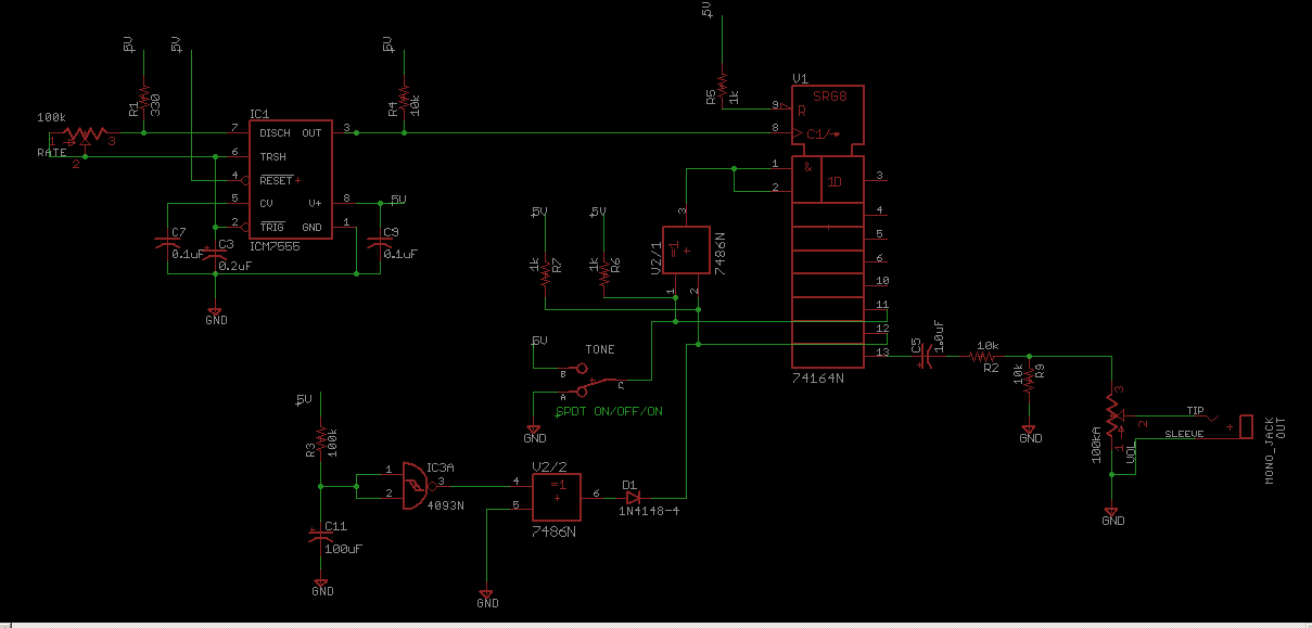
Schematic for the CMOS Linear Feedback Shift Register Vintage Atari Sound Effects Generator circuit. The circuit design consists of a CMOS Linear Feedback Shift Register (LFSR) that is utilized to generate sound effects reminiscent of vintage Atari games. The LFSR...
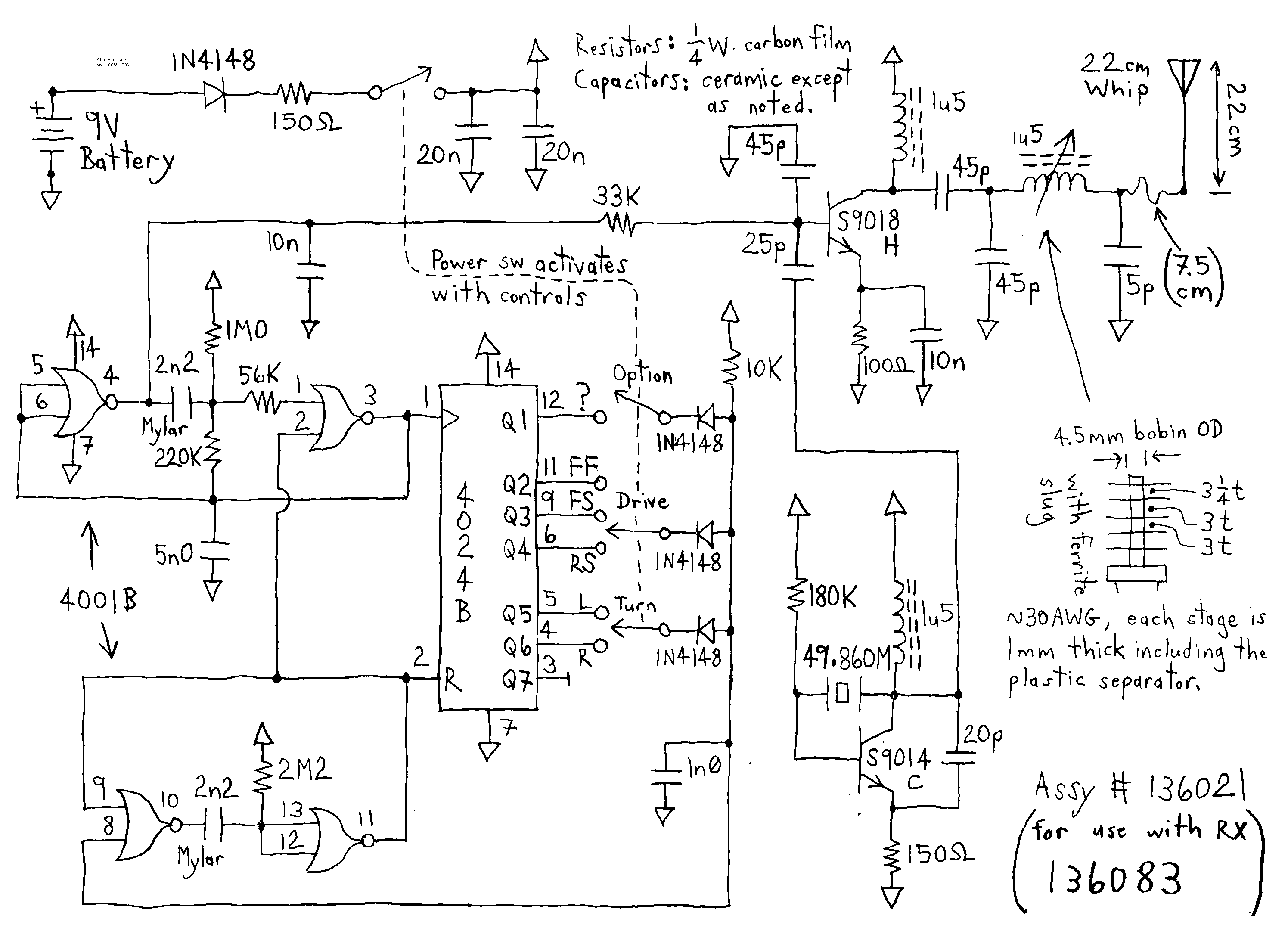
The receiver is equipped with a larger motor to drive the wheels and a smaller motor for steering, which operates in a non-proportional manner. An additional channel can be incorporated into the receiver by utilizing the spare latch. The...
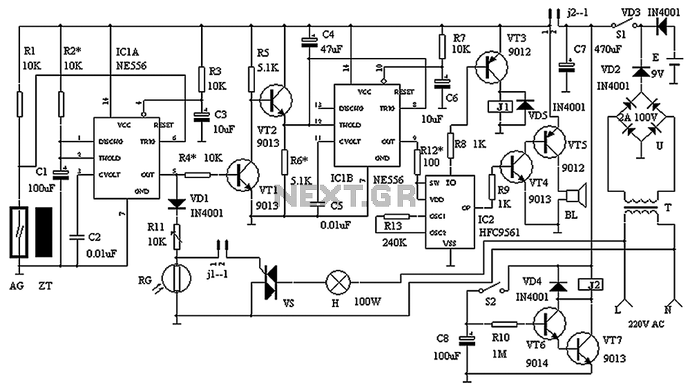
The circuit consists of a triggering device, a monostable delay circuit, an alarm sound generator, an audio amplifier circuit, and a light control circuit, with a partially blocking preset circuit and power circuit. When the door is locked and...
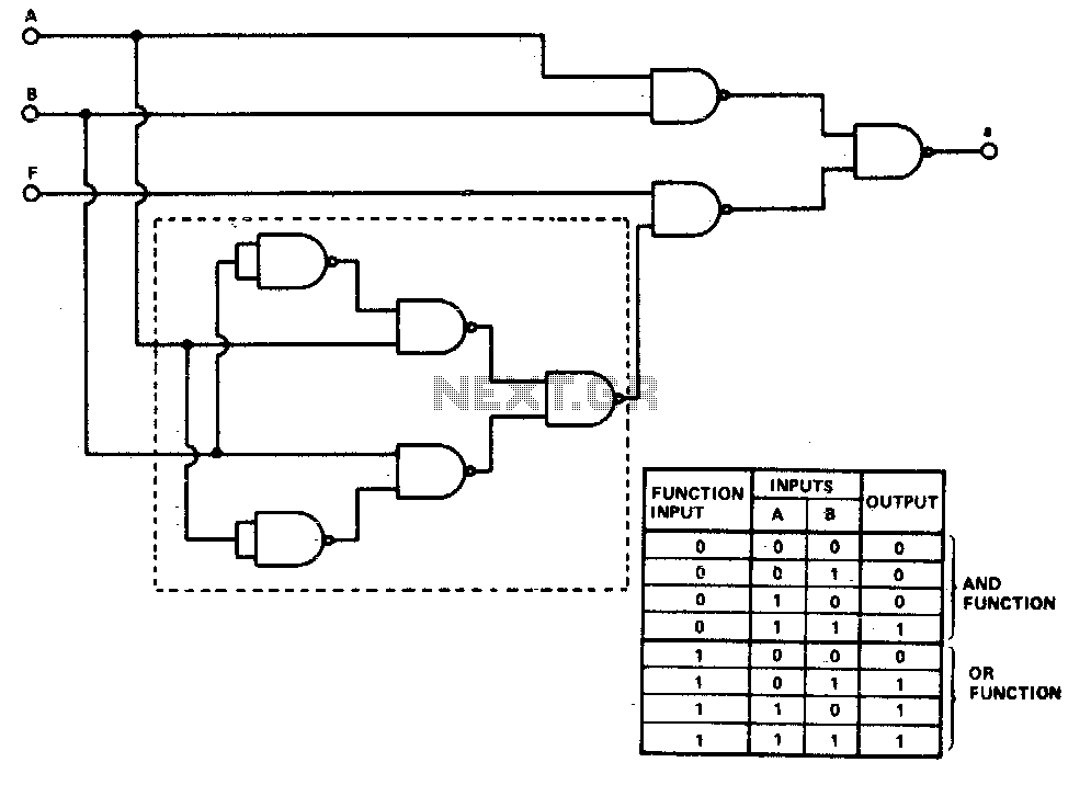
This gate converts an AND gate or an OR gate by applying a logic 1 on the function input. The logic design utilizes eight two-input NAND gates. The number of gates may be reduced by replacing the five NAND...
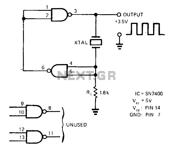
A SN7400 quartz crystal and a resistor provide a square-wave output of approximately 3.5 V. The circuit operates reliably at frequencies from 120 kHz to 4 MHz. The circuit utilizes a SN7400 integrated circuit, which is a quad two-input NAND...
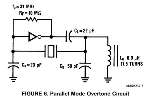
With the advent of high speed HCMOS circuits, it is possible to build systems with clock rates of greater than 30 MHz. The familiar gate oscillator circuits used at low frequencies work well at higher frequencies and either LC...