
CMOS LFSR Vintage Atari Sound Effects Generator
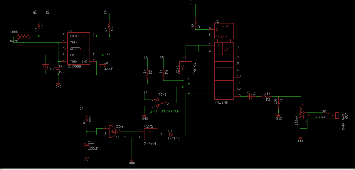
The circuit design consists of a CMOS Linear Feedback Shift Register (LFSR) that is utilized to generate sound effects reminiscent of vintage Atari games. The LFSR operates by shifting bits through a series of flip-flops, where the output of certain flip-flops is fed back into the input through a series of exclusive OR (XOR) gates. This feedback mechanism creates a pseudo-random binary sequence, which can be manipulated to produce various sound effects.
The schematic typically includes a series of CMOS integrated circuits, which are known for their low power consumption and high noise immunity. Key components include the shift register, which may be implemented using 74HC595 or similar CMOS shift register ICs, and the XOR gates that determine the feedback configuration. The output from the LFSR can be connected to a digital-to-analog converter (DAC) to produce audible sound waves, or it can be fed directly into a speaker driver circuit.
The configuration of the XOR gates is crucial, as it defines the polynomial characteristic of the LFSR, thereby influencing the sequence of bits generated. Common configurations can be found in literature that describe specific tap positions for different lengths of registers (e.g., 4-bit, 8-bit).
Additionally, capacitors and resistors may be included in the circuit to filter the output and shape the sound waveforms, providing a more refined audio output. Power supply considerations are also important, ensuring that the circuit operates within the specified voltage range for the CMOS components.
Overall, this schematic serves as a foundational design for creating sound effects that capture the essence of classic Atari games, making it a valuable resource for hobbyists and engineers interested in retro gaming technology.Schematic for the CMOS Linear Feedback Shift Register Vintage Atari Sound Effects Generator circuit.. 🔗 External reference
Related Circuits

A sound-detecting alarm system can be constructed using a microphone, a high-gain amplifier, and a detector-relay driver. For a latching setup, connect the dotted lines to the relay as indicated in the schematic. The sound-detecting alarm system utilizes a microphone...
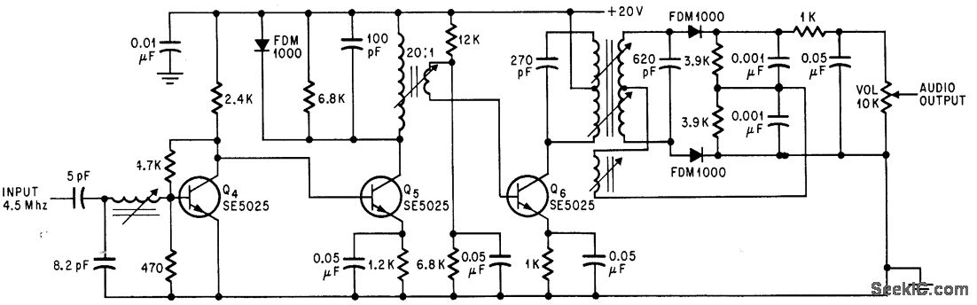
Utilizes three transistor stages and a Foster-Seeley discriminator to produce an audio output of 1 V peak-to-peak. -D. Bray, Solid State Makes Debut in Big Screen Color TV, Electronics, 39:8, p 99-105. The circuit in question employs a combination of...
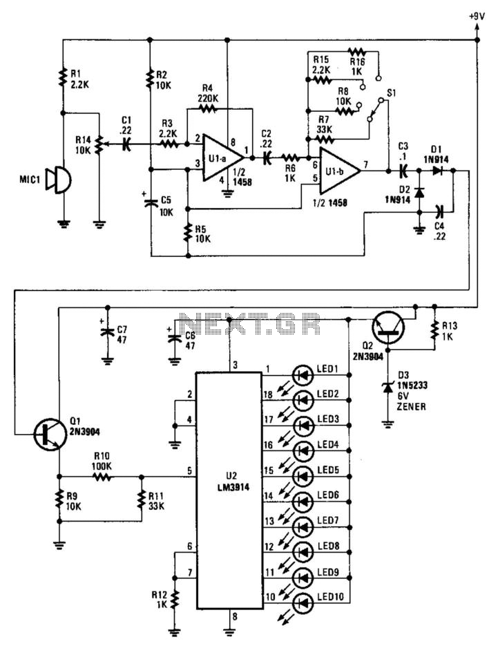
An electret microphone feeds an audio amplifier/rectifier combination. The amplifier has switchable gain. The rectifier output drives an LM3914 bar-graph generator. R14 provides fine gain control. The circuit begins with an electret microphone, which serves as the primary audio input...
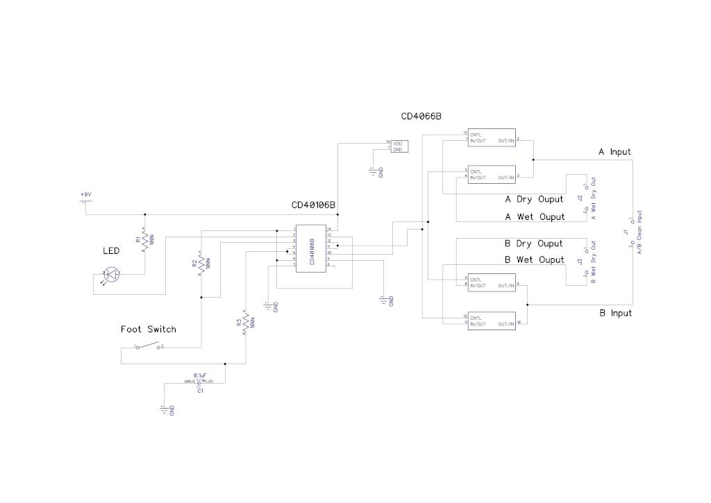
A simple audio switching circuit is experiencing issues. The circuit utilizes a CD40106 Schmitt Trigger in conjunction with a CD4066 CMOS switch to route audio signals. The circuit design incorporates a CD40106 Schmitt Trigger, which is essential for providing clean...
The Z86E02 is one of ZiLOG's most popular Z8 One Time Programmables (OTPs). It features a 512-byte EPROM, 61 bytes of RAM, 14 I/O ports, a Watch-Dog Timer, Power-On Reset, a Low-Voltage Protection circuit, and an additional Timer. Notable...
A high voltage power supply DC converter that operates between 3V to 500V has been suggested for use with Geiger tubes. However, during simulation, the output remained at nearly 9V, which matches the input voltage. The schematic drawn has...