
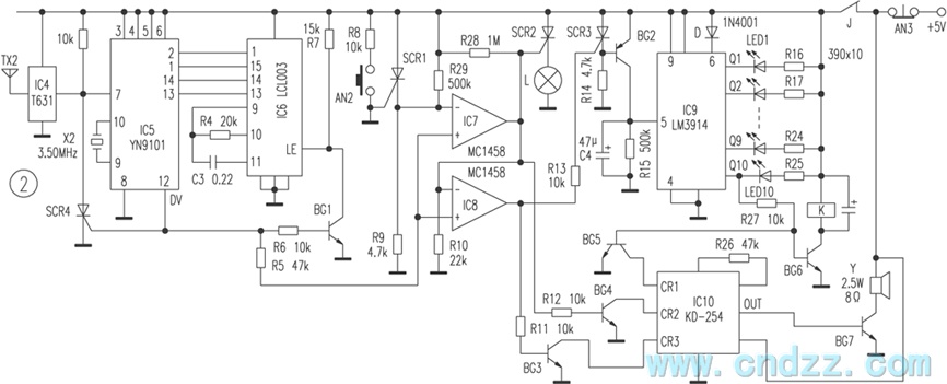
Practical gated burglar alarm circuit diagram

Once the door is opened, the separation of ZT AG causes the two contacts to open, which in turn brings the pin of IC1A low (less than 1/3 of the supply voltage), immediately setting IC1A from low to high. This leads to two actions: one, the triac triggers VS, turning on light H, which is intended for door illumination. If the door is opened during the day, the photoresistor RG's resistance is quite low, and the partial voltage across R11 and RG is insufficient to trigger conduction, meaning light H may remain off during the day. The second action allows current to flow through transistor VT1, causing VT2 to conduct, which releases the charge from capacitor C4. Power is then supplied to C4 through resistor R6, bringing the potential of pin 12 of IC1B low. When this potential drops below one-third of its power supply voltage, the output pin A of IC1B goes high, powering IC2.
IC2 generates pulse currents, which after amplification through transistor VT3, actuate relay contact J1-1, switching the original lights to a flashing state to enhance the alarm atmosphere. The output from IC2 also provides an audio alarm signal, which is amplified by transistors VT4 and VT5 to drive the speaker BL at a loud volume. The alarm will automatically stop after a set period, as IC1A operates in monostable mode, charging the voltage to 2/3 of the power supply voltage, which causes IC1A to reset and its output to revert to low.
The preset locking circuit is composed of transistors VT6 and VT7. When the power switch S1 is turned on, pressing switch S2 allows VT6 and VT7 to conduct, temporarily pulling relay J2's contact J2-1 off, thus cutting the power to the alarm circuit and preventing false alarms while the owner closes the door. When the door is secured, capacitor C9 discharges, causing VT6 and VT7 to close, releasing J2 and turning on the power supply for the oscillator circuit, placing the system in a waiting state.
The entire circuit is designed to be robust, and if all components are of good quality and correctly soldered, the system can be tested by closing ZT AG and turning on the power switch S1. Light H should remain off; upon removing ZT, light H should immediately turn on (a black cylinder can be used to test in daylight). Pressing S2 should turn off light H, and after a delay, light H should turn on again, indicating the oscillator is functioning and the siren is activated, with light H transitioning to a flashing state. The preset time for the blockade is determined by the value of 0.7R10C8, while the working time of IC1A in monostable mode is determined by the values of R2 and C1. The delay time is defined by the flip of IC1B, which can be adjusted through experimentation. The operating voltage for IC2 should not exceed 5V, and resistor R12 can be used for further adjustments.
For installation, AG should be mounted on the door frame, while ZT should be placed on the door leaf. The complete circuit can be housed in a milky white plastic cover installed in the ceiling. Before leaving, the owner can engage the pre-alarm by closing switch S1 and pressing S2, which will prepare the system for the waiting state. If the owner opens the door at night, light H should illuminate automatically. If the indoor light switch is found, the owner should immediately disconnect the hidden power switch S1 to avoid triggering the alarm. If a thief attempts to open the door, the alarm will sound after a delay, serving as a deterrent. Circuit as shown by the triggering device, monostable delay circuit, the alarm sound generator, audio amplifier circuit, light control circuit, partially blocking the preset ci rcuit and power circuit. When the door locked and a permanent magnet ZT normally closed reed AG in close proximity, ZT AG magnetic field lines resulting in two separate contacts, so IC1A of foot was high, IC1A in the reset state, which output terminal pin is low, no VS triac trigger current blocking, it lights H is off. At this time no bias transistor VT1 off, VT2 are conduction, so IC1B of 12, feet was high (greater than 2/3 of the supply voltage), it is also IC1B the a feet output low, audio IC IC2 does not work without power.Once the door is opened, resulting in ZT AG and separated the two contacts within the AG naturally turned on, the cause IC1A pin goes low (less than 1/3 of the supply voltage), then immediately set IC1A, IC1A of feet from the original low to high, it is divided into two branches: one triac trigger VS conduction, H lights immediately lit, which can be used for lighting by the door.
If the door during the day, since the photoresistor RG resistance is very small, the partial pressure of R11 and RG VS is not sufficient to trigger conduction, so during the day the door, H may not light. Another way to make the current transistor VT1 conduction, VT2 end result, short condition C4 is released, power to the C4 charge through R6, at this time IC1B of 12, feet potential of getting low, when less than one-third of its potential power voltage, IC1B output terminal a pin goes high, then the IC2 power and get to work.
There have been the end of IC2 T0 pulse currents, after amplifying transistor VT3, pushing J1 relay contact j1-1 move and opened, thus making the original lights become constant light flashing lights to enhance the tension when the alarm the atmosphere, the same O/P end to IC2 output audio alarm signal, the VT4, after VT5 zoom, push the speaker BL loud voice.The alarm device for some time, the thief away, its siren can be automatically stopped. This is because IC1A was monostable mode, be it O, feet charge voltage to 2/3 of the power supply voltage, IC1A automatically reset, IC1As feet will automatically revert to a low level.Preset locking circuit by the transistor VT6, VT7 composition, after turning the machine power switch S1, should press the switch near S2, so VT6, VT7 conduction, the relay J2 temporarily pull its contacts j2-1 off, cut off power alarm circuit, so the owner closed the set alarm time does not cause false alarms.
When the door is good, C9 discharged, VT6, VT7 closing, J2 release, its contact j2-1 closed, the power supply of the oscillator circuit is automatically turned on, the machine is in the waiting state.Good quality as long as the entire circuit element, and the welding is correct, you can boot test, the first close ZT AG, close the power switch S1, H should not light goes out, then took ZT, H at this time should immediately lit (if in the daytime test application hooded black cylinder RG), and then press down S2, H at this time should be immediately extinguished, after waiting for some time, H lit again, after a period of time H is lit, the oscillator trigger job, issue loud siren sound, and by the constant light begins flashing H will come to create successful.Preset time determined by the blockade 0.7R10C8 value. IC1A monostable 1.1R2C1 working time is determined by the value, the delay time is determined by the flip IC1B 1.1R6C4 value, can be adjusted by experiment.
IC2 operating voltage should not exceed 5V, plus R12 can be adjusted.Installation and UseAG should be installed on the door frame, ZT should be installed on the door leaf activity, the entire circuit can be loaded into a milky white plastic cover in the ceiling.When the owner went out pre-alarm, can be closed S1, then press down S2, so until then lock the door, the alarm will automatically enter the waiting state. When the home owner with a key to open the door, if it is at night, when the door H lights automatically light up, the owner found the indoor light switch, should immediately disconnect the hidden power switch S1, otherwise it will cause an alarm.
And after the thief door, because it is not time to cut off the power switch on the alarm (do not know or could not get with a switch), it will be delayed several seconds after the siren rang out, attracting attention, to play a thief deterrent and to scare away.
Related Circuits
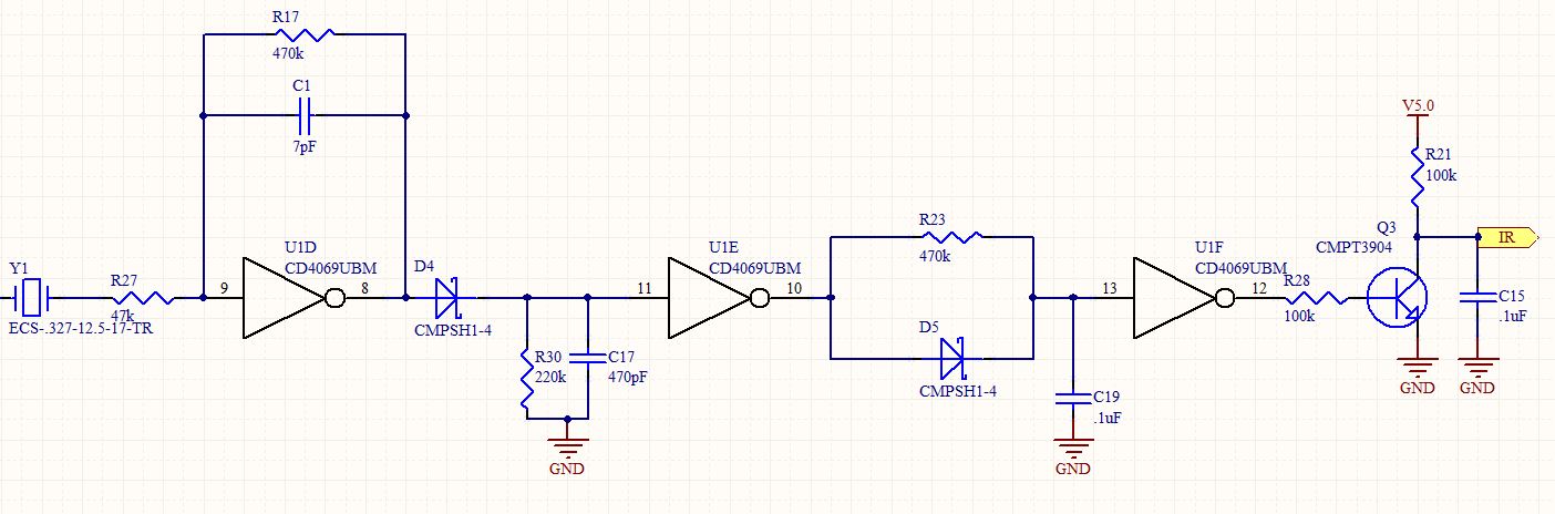
This is a follow-up to an earlier post regarding a specific circuit schematic. The circuit is designed to operate at a supply voltage of 5V, and testing has confirmed that the original device functions correctly at this voltage. A...
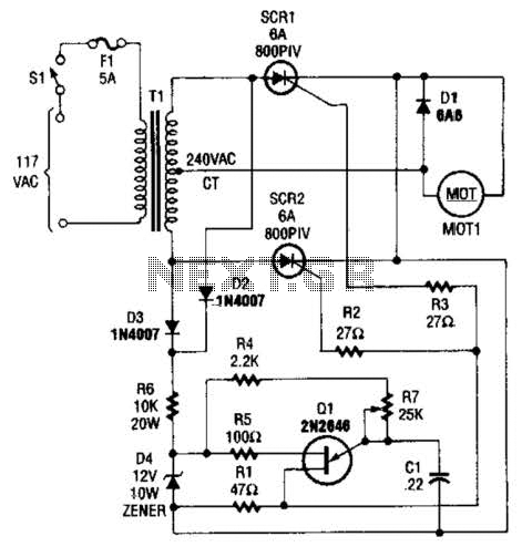
The speed-control switch provides effective control and stability across its entire operating range. This circuit utilizes two SCR devices arranged in a full-wave configuration to manage the DC power supplied to a motor. A center-tapped transformer is employed to...
This amplifier circuit integrates the LT1010 with a fast discrete stage and employs an LT1008-based DC stabilization loop. It features a differential stage that operates in a single-ended configuration. The described amplifier circuit is designed to enhance signal amplification while...

The circuit consists of two balanced components forming a simple Beat Frequency Oscillator (BFO) metal detector. The BFO utilizes a ready-assembled and tested circuit board with a PIC 12F675 chip at its center. This passive detector employs a detector...

The integrated circuit (IC) is a multistandard vision and sound intermediate frequency (IF) phase-locked loop (PLL) demodulator that operates without the need for alignment. It supports multiple television standards, including PAL, SECAM, and NTSC, and is capable of handling...
The wireless calling device consists of a calling unit and a host. These two components communicate using a DTMF encoder pulse. Each calling unit is assigned a unique code, although the circuits are identical. The calling unit is depicted...