
Reverse engineering the Elco heating protocol

The next consideration involves the time dimension and the type of line coding used. This can be determined by applying various schemes to see which one aligns. In this case, it appears to be a regular unipolar non-return-to-zero format. At this stage, it remains unclear whether the 12V corresponds to a binary 1 or 0.
Upon closer examination of the bit sequence, it can be observed that bit 0 mod 11 is low, while bit 10 mod 11 is high. This pattern resembles the bitstream generated by UARTs, which typically includes a start bit, 8 data bits, a parity bit (even in this instance), and a stop bit.
Given the similarities to the RS-232 protocol, it is anticipated that conversion between the BSB and RS-232 will be straightforward, allowing for further processing in software based on bits rather than voltages.
- The bus operates with +12V idle, while RS-232 expects an idle voltage of -3 to 15V.
- The bus begins communication with a start bit of 0V; RS-232 requires a start bit of +3 to 15V (logical 0).
- The bus sends data as 12V=0 and 0V=1, whereas RS-232 expects data to be -3 to 15V=1 and +3 to 15V=0.
- The bus uses even parity, while RS-232 can be configured for even, odd, or no parity.
- The bus concludes with a stop bit of 12V; RS-232 expects a stop bit of -3 to 15V (logical 1).
To ensure proper recognition of the bytes, a mapping from +12V to -3 to 15V and from 0V to +3 to 15V is required. This adjustment aligns the idle, start, data, and stop bits, but inverts the data bits and thus affects the parity.
In designing a circuit to interface with the QAA75 sensor via the Boiler System Bus (BSB), careful consideration must be given to the voltage levels and signal timing. A level-shifting circuit may be necessary to convert the voltage levels from the BSB to the RS-232 standard. This could involve using a combination of transistor-based level shifters or dedicated level-shifting ICs to ensure that the signal integrity is maintained while transitioning between the two protocols.
Additionally, implementing a microcontroller with UART capabilities would facilitate the processing of the received data. The microcontroller can be programmed to interpret the incoming signals according to the identified bit structure, allowing for effective communication with the sensor. The software should also account for the parity settings to ensure accurate data transmission and reception.
Overall, the design must ensure compatibility between the BSB and RS-232 standards while maintaining the reliability and accuracy of the communication process. Proper filtering and noise reduction techniques should also be considered to enhance the robustness of the system in real-world applications.First step is always to look around on the internet. After some searching, I found out that the QAA75-sensor is actually made by Siemens. This broadened my search a bit. Turns out that Siemens refers to the communication as a “Boiler System Bus (BSB)”. This is the first interesting piece: a bus. In contrast with the OpenTherm protocol, which is point-to-point, this name seems to indicate it’s a bus (which is point-to-multipoint). There are a lot of implications: 1) data is most probably transmitted in the voltage, not in the current, and certainly not both.
2) it should be possible to passively listen in on the conversations. 3) it should be possible to act as an additional device on the bus and transmit messages, without changing the bus wiring...
So we have the amplitude conquered, next up in the time dimension: what form of line code is used? Figuring this out just boils down to trying to apply the different schemes and seeing if they add up.
This particular case looks like very regular unipolar non-return-to-zero. At this point, it’s not clear whether the 12V corresponds to a binary 1 or 0.
One can also see (after staring at the bit sequence for long enough) that bit 0 mod 11 is low; and bit 10 mod 11 is high. This looks very familiar to the bitstream produced by UARTs: a start bit, 8 data bits, a parity bit (odd even in this case) and a stop bit.
Since the protocol resembles RS-232 a bit, I figured it should be easy to convert from/to RS-232 and do the rest of the processing in software on bits instead of on voltages.
- The bus uses +12V idle; RS-232 expects -3~15V idle
- The bus starts with a startbit of 0V; RS-232 expects a start-bit of +3~15V (logical 0)
- The bus sends data
12V=1, 0V=012V=0, 0V=1; RS-232 expects data -3~15V=1, +3~15V=0 - The bus sends even parity; RS-232 can be configured for even, odd or no parity
- The bus sends a stopbit of 12V; RS-232 expects a stop-bit of -3~15V (logical 1)
So in order to have the bytes correctly recognized, we need to map +12V -> -3~15V and 0V -> +3~15V.
This causes the idle, start, data and stop-bits to match, but inverts the data-bits and hence the parity...
The above content was licensed from Niobos: https://blog.dest-unreach.be - under the CC-BY-NC-SA - https://creativecommons.org/licenses/by-nc-sa/2.0/be/deed.en_US license.
🔗 External referenceRelated Circuits
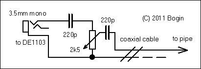
If residing in a flat with steel central heating pipes and lacking the option to install an external antenna due to thermal insulation, this indoor shortwave antenna may be the optimal choice for portable world band radios in terms...
A DC supply of +5 V is obtained from a 230 V AC source. This power supply is utilized by other circuit blocks. A pulse generator operating at a specific frequency generates clock pulses. These clock pulses are counted...
The DS protocol was designed to provide firmware-based bidirectional host-to-slave interprocessor communications for situations in which no hardware solution is available and the host and/or the slave is incapable of tending the interface in real time. The only specialized...
Embedded systems serve as the core of most electronics-based systems, enabling data access, processing, storage, and control. While some simple electronic circuits can be designed without a microprocessor or microcontroller, this approach is often economically impractical, except for basic...
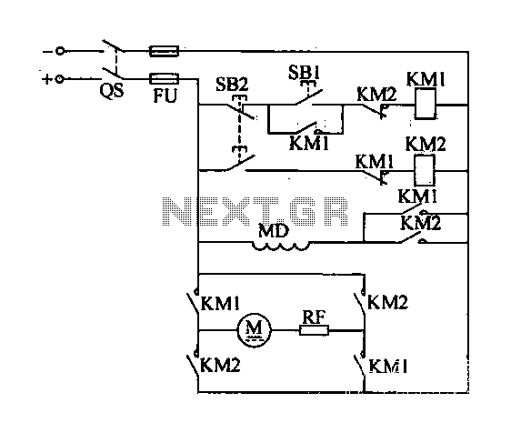
A DC motor reverse brake circuit is presented. To initiate braking, the stop button (SB2) is pressed, which disconnects the move-off contact, causing KM1 to lose power and release. Subsequently, the brake contactor (KM2) is activated. KM2 is designed...
DMRC's uniqueness lies in how it has managed soft issues related to the general public affected by it. To alleviate traffic congestion and chaos around construction sites on main roads, DMRC deployed special personnel to assist Delhi Police. Cars...