
Central heating pipe antenna for SW
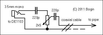
The circuit presented is a straightforward example of a receiver antenna attenuator. It is advised to use short connections for the input jack. The potentiometer should be used in conjunction with the internal attenuation circuitry of the world band radio to avoid overloading. If excessive noise or station bleed occurs during reception, increasing the resistance between the antenna jack and coaxial cable is recommended. The center conductor of the coaxial cable should be connected directly to an exposed section of the heating pipes, ensuring that the section is free of paint or lacquer. The shielding should only connect to the negative terminal of the receiver. It is crucial to avoid using this antenna with any receiver that is grounded, as the steel heating pipes are electrically connected to ground. This restriction means that the antenna is suitable for portable, battery-operated world band radios.
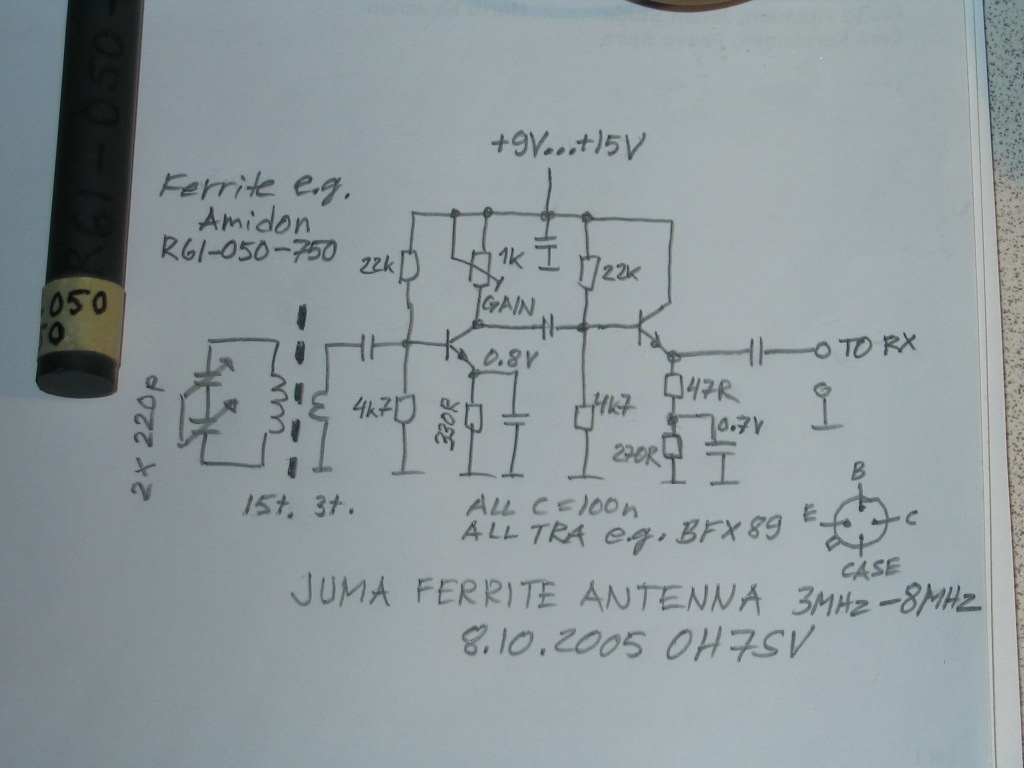
The rationale behind this limitation is that connecting the setup to a desktop receiver or an SDR powered by mains electricity may lead to improper operation or significant interference (QRM). This is akin to shorting the antenna jack directly to the mains ground. Conversely, this setup is advantageous for battery-powered radios, as the ground serves as a zero-volt potential, functioning like a lightning conductor and protecting the input stage from static or electrical charges. For those with a desktop receiver or any device connected to mains ground interested in this setup, a ferrite antenna can be constructed using suitable ferrite cores with the central heating pipes at the center. Alternatively, winding 10-15 turns around the pipes can be attempted, although this may introduce interference from nearby objects unless appropriately shielded.
This configuration represents a practical solution for enhancing shortwave reception in environments where traditional antenna installations are not feasible. The careful consideration of grounding and shielding is essential to optimize performance and minimize interference.If you happen to live in a flat with steel central heater pipes and you don`t have the option to make yourself an external antenna, due to e. g. thermal insulation, this might probably be the best indoor shortwave antenna for portable world band radios; when it comes to signal (or noise) strength.
The latter happens in unfortunate cases, when there are just many switched mode-based modern electronics around. However, along with a simple attenuating circuit, it beats any indoor long- or random-wire setup. I use this indoor gizmo on my Degen DE1103 for casual shortwave number or oddity stations hunting; and the results were spectacular: positioned in central Europe in a block of flats, I have managed to catch Cuba, Libya, Vietnam or even Bangkok with this setup, besides other stations. So, here`s how! As you can see, this circuit is the simplest example of an RX antenna attenuator. For the input jack, use as short connections as possible. Use the potentiometer in combination with the internal attenuation circuitry of your world band radio to prevent overloading.
Thus, if there`s too much noise in your reception, or stations bleeding through , increase resistance between the antenna jack and coaxial. Then, connect the center conductor of your coaxial directly to any uncovered part of your pipes (find one with no paint/lacquer), and it`s done.
Shielding is connected only to the negative pole of your receiver, please see the note below. Do not try to use this antenna on any receiver which is connected to ground. Or, in other words, this antenna can be used for portable, battery-powered world band radios, as mentioned above. Why this limitation Technically, steel central heating pipes are directly connected to ground, both literally and electrically.
Thus, if you try to connect this setup to a desktop receiver, or to an SDR powered by a computer running on mains, it might not work properly, or it will introduce a lot of QRM (interference). It would be like shorting your antenna jack directly to mains ground. On the other hand, this is actually a big advantage for battery powered radios; since ground acts as a zero volt potential like a lightning conductor, this setup will also protect your input stage from any static or electrical charges.
If you own a desktop receiver (or any other connected to mains ground in general) and you are still interested in this setup, you will need to make a ferrite antenna out of some suitable ferrite cores, with the central heating pipes in center, like this. Or, try directly winding some 10-15 turns on the pipes. However, you might introduce interference from anything which is near this coil , unless you shield it someway.
🔗 External reference
Related Circuits
The Anderson Loop is a basic detector that is often not referred to by this name among amateur radio operators, with the term primarily used by those who patented the design. A notable application of this detector is found...
This blog showcases various electronics circuit designs, applications, fields, and resources that can assist students, engineers, professionals, and anyone interested in electronics. For comments, suggestions, or inquiries about circuits, designs, or electronics designers, please contact [email protected]. The blog is...
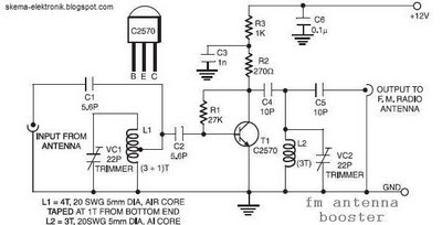
The coil L2 is tapped at the first turn from the ground lead side and is similar to coil L1, but consists of only three turns. The pin configuration of the transistor 2SC2570 is illustrated in the FM antenna...
The red connector is designated for an optional external antenna wire, while the black connector serves as the ground wire. The red wire is connected to the secondary winding, and the black wire is linked to the circuit ground...
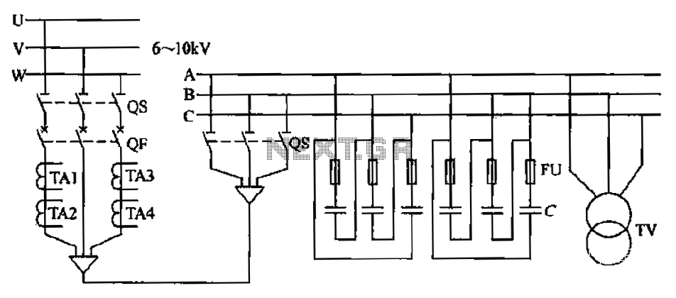
The compensation system is designed to focus on a high-pressure, high-voltage capacitor bank installed in the substation 6-10 kV bus. Compensation can only be implemented in this manner for the 6-10 kV bus before the reactive power on the...
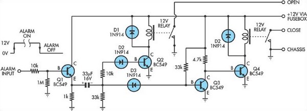
Some inexpensive car alarms lack a connection for the central locking system. However, in most cases, it is possible to identify a point in the alarm circuit that outputs a high signal when the alarm is activated and a...