
RF Circuitry Links
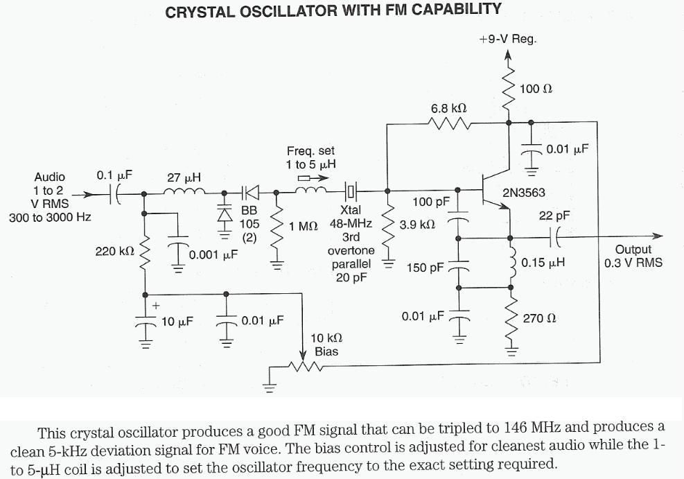
The 7th overtone of an 18 MHz signal, which resonates at 144 MHz, occupies a critical position within the Continuous Wave (CW) region of the radio spectrum. This frequency is relevant for various communication applications, including amateur radio. The Icarus project exemplifies innovative uses of high-altitude balloons in capturing aerial imagery, supported by a sustainable funding model through advertising.
"Lessons in Electric Circuits" serves as a foundational resource for electronics enthusiasts, providing comprehensive coverage of essential concepts. New learners are encouraged to familiarize themselves with pertinent chapters to build a solid understanding of electronic principles.
The 1W CW transmitter kit is notable for its efficient design, utilizing a 74HC04 buffer chip, which functions as both an oscillator and an initial amplification stage. This configuration is typical in low-power radio frequency (QRP) applications, where minimizing power consumption is crucial. The subsequent amplification stage employs a 2N3866 transistor, which is well-regarded for its performance in RF applications.
The 30M Solar QRSS transmitter showcases advancements in solar-powered technology and innovative design strategies. By using a 74HC245 buffer chip to amplify the output from a microcontroller, the system achieves efficient operation at the designated transmission frequency. The incorporation of a temperature compensation mechanism utilizing the chip's thermosensor to adjust the output offset is particularly noteworthy, as it enhances stability in varying environmental conditions—a technique not commonly seen in QRP transmitters.
The QRSS receiver circuit based on the SA602 chip demonstrates the practical application of integrated circuits in low-power reception scenarios. The replication of this circuit for the W4DFU QRSS Grabber at the University of Florida indicates its effectiveness in capturing weak signals.
Finally, the document on "MOSFET Switched Mode Amplifiers" highlights the advantages of using MOSFETs in QRP circuits. Their unique characteristics, such as high input impedance and efficient switching capabilities, allow for simpler circuit designs while maintaining performance. The guide is an invaluable resource for those looking to deepen their understanding of these components in the context of RF amplification.The 7th overtone of 18mhz (17m) is 144mhz (2m) smack dab in the CW region. Icarus a HAB project run on advertising revenue that seems successful and has launched many balloons with some awesome photos. Robert Harrison knows his stuff! Lessons in Electric Circuits A very good (free) textbook. Anyone starting to learn about electronics should start by skimming over relevant chapters of this text! 1W CW transmitter kit Although I don`t own one, I appreciate the kit and love the schematic. This guy uses a buffer chip (a 74HC04n, similar to a 74HC240 often used in QRP too) to act as an oscillator and small amplifier. The output is then further amplified by a 2n3866 transistor. 30M Solar QRSS transmitter such an inspiring project! This guy uses a buffer chip (74hc245) to amplify the output of CKOUT of a microcontroller clocked at the transmit frequency.
The thing is solar powered, and has a unique temperature compensation mechanism which uses the chip`s built-in thermosensor to adjust its offset. I haven`t seen this technique used anywhere else in a QRP transmitter! Everything this man does is impressive! His QRSS section is wonderful, and I won`t detract from it by trying to describe it here. He also has a simple QRSS receiver circuit based upon a SA602, something I replicated (tuned front-end not shown) to operate my W4DFU QRSS Grabber at the University of Florida.
MOSFET Switched Mode Amplifiers a wonderful document, read it multiple times! Transistors are traditionally used in many QRP circuits as amplifiers, but MOSFETs have some unique qualities which in many ways makes them easier to work with in simple circuits. I found this guide EXTREMELY helpful! 🔗 External reference
Related Circuits
Assistance is required regarding the circuits provided below. The focus is on an ultrasonic receiver circuit that utilizes two ultrasonic components. The ultrasonic receiver circuit is designed to detect ultrasonic waves, typically in the frequency range of 20 kHz to...

The circuit depicted in Figure 3-190 includes an armature circuit with two startup resistors, Ri and Rz, connected in series through the main switch SA to facilitate starting, stopping, and speed control. During the startup phase, two relays, KTi...
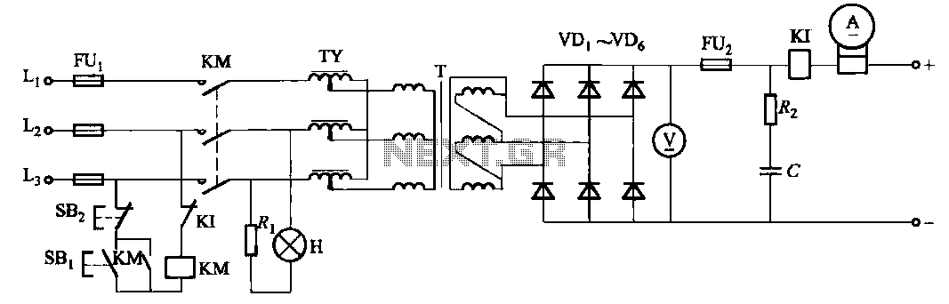
There are a total of four types of specifications for a three-phase bridge rectifier circuit. The output voltage is regulated by a TY regulator. The three-phase bridge rectifier circuit is designed to convert three-phase alternating current (AC) into direct current...

Power Integrations' DER322 reference design employs the LinkSwitch-PL family of LNK460VG devices. This design represents the industry's first alternative 100W A19 incandescent LED driver utilizing a single-layer PCB. It is characterized by low cost, minimal component count, and compact...

AN12979A is a stereo BTL amplifier that includes an AGC circuit to prevent clipping at the speaker output. This integrated circuit (IC) can perform mode changes via the I2C bus control system, allowing for functions such as toggling the...

This document outlines the process of adding hardware to a Linksys WRT54GL wireless router to utilize existing connections on the PCB for two UART connections. These connections will be made available as DB9 serial port connectors mounted on the...
Warning: include(partials/cookie-banner.php): Failed to open stream: Permission denied in /var/www/html/nextgr/view-circuit.php on line 713
Warning: include(): Failed opening 'partials/cookie-banner.php' for inclusion (include_path='.:/usr/share/php') in /var/www/html/nextgr/view-circuit.php on line 713