
Opamps and ultrasonic receiver circuitry
The ultrasonic receiver circuit is designed to detect ultrasonic waves, typically in the frequency range of 20 kHz to several MHz, which are beyond the range of human hearing. This circuit is often used in applications such as distance measurement, object detection, and various forms of non-contact sensing.
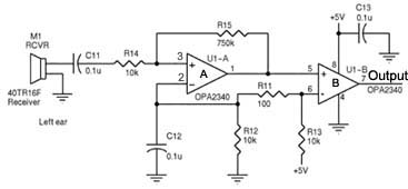
The core components of an ultrasonic receiver circuit include an ultrasonic transducer, which converts ultrasonic sound waves into electrical signals. In this design, two ultrasonic transducers are employed: one for transmitting ultrasonic pulses and the other for receiving the reflected waves. The transducers are usually piezoelectric devices that respond to high-frequency signals.
The circuit may incorporate an amplifier to enhance the weak signals received by the transducer. This amplifier is typically a low-noise operational amplifier configured in a non-inverting or inverting configuration, depending on the desired gain and signal processing requirements. The output from the amplifier can be fed into a microcontroller or a comparator circuit for further processing.
Additionally, a filter may be included to eliminate noise and ensure that only signals within the desired frequency range are processed. This filter can be a band-pass filter designed to allow ultrasonic frequencies while attenuating lower and higher frequencies.
For distance measurement applications, the circuit may also feature a timing mechanism, such as a microcontroller, which calculates the time taken for the ultrasonic pulse to travel to an object and back. By knowing the speed of sound, the distance to the object can be accurately determined.
Power supply considerations are crucial in designing the circuit. A stable power source ensures consistent performance of the ultrasonic transducers and associated circuitry. Voltage regulators may be used to provide the necessary operating voltage levels for the components.
To summarize, the ultrasonic receiver circuit operates by transmitting ultrasonic pulses, receiving the echoes, amplifying the signals, filtering out noise, and processing the information to determine distance or detect objects. This makes it a versatile solution for various sensing applications in electronics.Hi! I desperately need help concerning the circuits I`ve attached below. Basically, it is an ultrasonic receiver circuit, with two ultrasonic.. 🔗 External reference
Related Circuits
Building a practical and usable direct conversion receiver for the 40 m CW band is not as simple as it might appear. Broadcast station signals from the adjacent 41 m band will easily overload most direct conversion mixer designs...
The image depicts an ultrasonic liquid level indicator circuit. This circuit consists of an ultrasonic transmitter circuit and a receiver circuit. The ultrasonic transmitter circuit includes a 555 timer, resistor R1, variable resistor W1, capacitor C1, and the ultrasonic...
The regenerative detector uses a field effect transistor (FET). Like with the better valve designs, feedback is controlled by a variable capacitor. A ferrite rod was used to allow reception of local stations without an external antenna. This FET...
The CD-ROM 48X RF AMP Chip serves as an RF pre-signal processor, handling signals from the optical pick-up. This chip processes the primary signal through a summing amplifier, an automatic gain control (AGC) block, and an equalization (EQ) block,...
The SC41343 is designed as a type of infrared, ultrasonic, or RF remote control launch coding circuit. The internal circuit comprises a sequence generator, control logic circuit, 4-bit shift register, data extraction circuit, and latch circuit. Features include the...
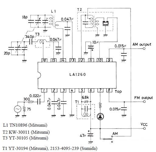
The FM IF MW radio receiver circuit schematic utilizes the LA1260 integrated circuit (IC) for AM and FM radio receiver electronic projects. The LA1260 incorporates numerous functions and features essential for radio receiver applications, including a high signal-to-noise ratio...