
RF data link and remote control

The only things that really need any tweaking to get the demonstration circuits to work is one hand wound inductor in the transmitter and one hand wound inductor in the receiver. The trick is to get the transmitter and the receiver on the same frequency. Having them "almost" on the same frequency will result in poor performance - very short range and unreliable decoding. Use a small wooden or plastic tool to deform the coils. Expect to spend some time at it, and don't be disappointed if you have to scrap a coil or two before you feel you have it right. Make and adjust the transmitter first. This way, you know what frequency you are using. Adjust the receiver for peak sensitivity to the transmitter.
A pulse frequency modulated pulse train is used to amplitude modulate an RF carrier (in on-off fashion) and detected and made digital in a simple receiver and this pulse train is decoded by a microcontroller.
The assembly code for the encoder and decoder were written with the AT90S1200 and ATtiny12 in mind in that they make minimal use of the return stack. The code was initially tested on AT90S2313's.
If you are using an ATtiny12, be careful not to disable the reset input, disable the SPI interface, or select a wacky clock mode or the chip may become unprogrammable with an in-system programmer (ISP). If you can use a part with fewer security features, like the AT90S1200 or AT90S2313, you will be safer. If you want to use the ATtiny12 you will probably need something that can restore these fuses using the high voltage serial programming algorithm, such as this ATtiny12 fuse restorer.
This circuit consists of a transmitter and receiver pair designed for low-power RF communication. The transmitter employs a simple oscillator circuit modulated by the encoder microcontroller, which generates a pulse frequency modulated signal. The output is transmitted over the air and is designed to operate in the 55 MHz frequency band, suitable for television channel 2 in the U.S.
The receiver utilizes a tuned radio frequency (TRF) detection method, which is effective for low-power applications. It does not include a preamplifier, relying instead on a 40 dB audio frequency (AF) amplifier to boost the signal before it is processed by a comparator. This comparator converts the received analog signal into digital pulses that can be interpreted by the decoder microcontroller.
Key components in this design include hand-wound inductors in both the transmitter and receiver circuits, which must be carefully adjusted to ensure that both units operate at the same frequency. This fine-tuning is critical for achieving reliable communication over the specified range of one to two meters. The choice of microcontrollers, such as the AT90S1200 or ATtiny12, allows for flexibility in implementation, although caution is advised regarding the configuration of the ATtiny12 to avoid rendering it unprogrammable.
Overall, the design emphasizes simplicity and cost-effectiveness while providing a functional RF data link suitable for short-range applications.This section describes an experimental low power, low bandwidth data signaling system that was initially made to operate at 55 MHz (television channel 2 in the U.S.). Before operating a radio transmitter, find out what kind of transmitter operation, if any, is permitted in your locality.
Radio transmitter operation is a serious legal matter. This design can be readily adapted to different frequencies and lower power levels. If you choose to build and operate the transmitter described here, you do so at your own risk. I'm only publishing this as an example of what can be done, and to show how easy it is to build a simple but functional receiver. This is a simple, low cost RF data link that can send data reliably over a distance of one to two meters, enough for bench top or desktop use. The data protocol supported by the encoder and decoder provides 16 device addresses, three message types, and a toggle bit.
Pulse frequency modulation is employed to make the receiver design less demanding and to reduce the susceptibility to noise. The encoder and decoder are based on Atmel microcontrollers, though the protocol can be easily implemented on most micro controllers.
The transmitter is an oscillator that is biased on and off by the encoder chip. The receiver is a tuned radio frequency (TRF) detector without preamp followed by an 40 db AF amplifier that drives a comparator, which provides pulses suitable for driving the digital input pin on the decoder. Most of the gain is provided by the op amp, where gain is easy and cheap, and the RF section is minimized and simplified.
The only things that really need any tweaking to get the demonstration circuits to work is one hand wound inductor in the transmitter and one hand wound inductor in the receiver. The trick is to get the transmitter and the receiver on the same frequency. Having them "almost" on the same frequency will result in poor performance - very short range and unreliable decoding.
Use a small wooden or plastic tool to deform the coils. Expect to spend some time at it, and don't be disappointed if you have to scrap a coil or two before you feel you have it right (more on this in the receiver section). Make and adjust the transmitter first. This way, you know what frequency you are using. Adjust the receiver for peak sensitivity to the transmitter. A pulse frequency modulated pulse train is used to amplitude modulate an RF carrier (in on-off fashion) and detected and made digital in a simple receiver and this pulse train is decoded by a micro controller.
The assembly code for the encoder and decoder were written with the AT90S1200 and ATtiny12 in mind in that they make minimal use of the return stack. The code was initially tested on AT90S2313's. Click on the links below for the particulars. Transmitter Receiver Data format Also see the tune-up section in RS-232 to 100 MHz Desktop Channel Adapter on this site for some additional tips on adjusting the receiver.
ATtiny 12 warning f you are using an ATtiny12, be careful not to disable the reset input, disable the SPI interface, or select a wacky clock mode or the chip may become unprogrammable with an in-system programmer (ISP). If you can use a part with fewer security features, like the AT90S1200 or AT90S2313, you will be safer.
If you want to us the ATtiny12 you will probably need something that can restore these fuses using the high voltage serial programming algorithim, such as this ATtiny12 fuse restorer. If you want to run your ATtiny12 on an STK-500, here are some step-by-step instructions I wrote for one of the users of this site.
He was kind enough to provide feedback resulting in a fully debugged procedure. 🔗 External reference
Related Circuits
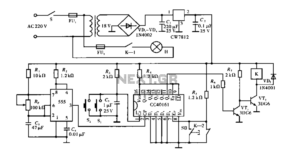
Corridor counter delay circuit for controlling lights. This circuit is tested and functional. When the circuit is energized, the 555 oscillator starts to oscillate. The CC40161 is cleared, and an integrating circuit composed of R3 and C5 transitions the...

Tone controls are often discouraged in high-end audio systems. However, one might argue that a high-end audio cable functions similarly to a high-end tone control. It is possible to purchase or... Tone controls in audio systems serve to adjust the...
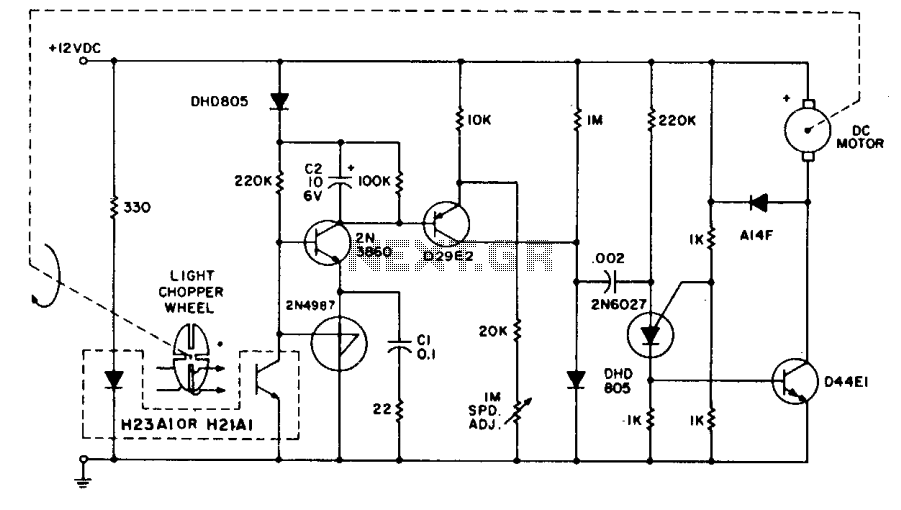
The system employs the H21A1 optocoupler and a chopper disc to achieve enhanced speed regulation. This is effective when the dynamic characteristics of both the motor system and the feedback system are appropriately matched, ensuring stability. The tachometer feedback...
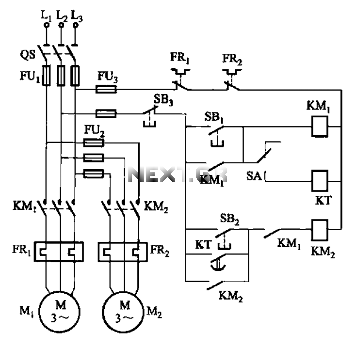
The circuit illustrated in Figure 3-85 features both manual and automatic control through the transfer switch SA. After initiating the motor Mi, an automatic start sequence is achieved via the time relay KT. The circuit employs a transfer switch (SA)...
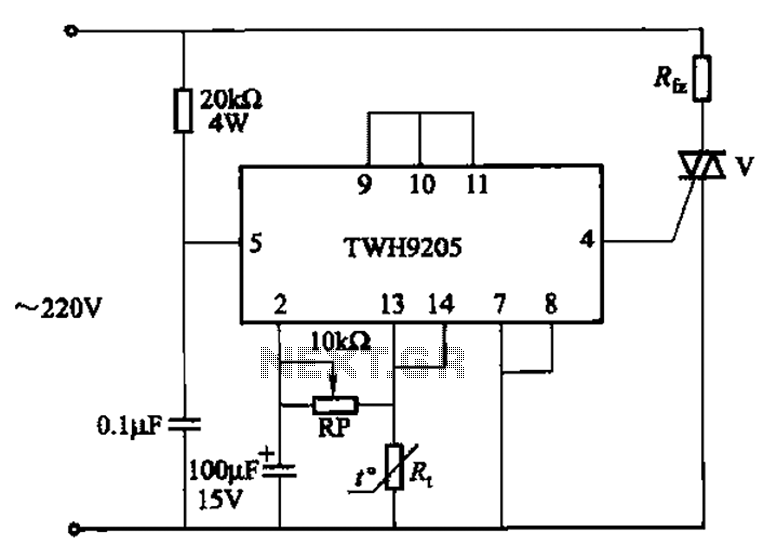
This circuit is used for temperature control in various heating equipment such as water heaters, microwave ovens, air conditioners, refrigerators, fans, and automatic fire extinguishing devices. It includes a negative temperature coefficient (NTC) thermistor as the temperature sensing element...
The aim of this project was to get a digital camera into a small electric radio controlled (RC) aeroplane and still have it fly. The aeroplane shown, a park flyer, weighs between 400 and 550 grams depending on the...