
Tachometer feedback control
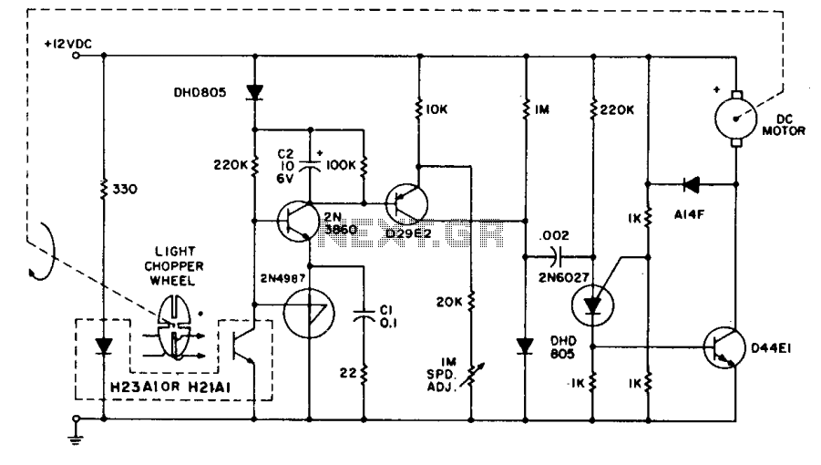
This DC motor control system incorporates an optochopper circuit that was previously demonstrated, which regulates a Programmable Unijunction Transistor (P.U.T.) pulse generator. The P.U.T. drives a D44E1 Darlington transistor, which in turn powers the motor.
The H21A1 optocoupler serves as a critical component in isolating the control circuitry from the high-power motor circuit, thereby protecting sensitive components from voltage spikes or noise generated by the motor. The chopper disc, rotating in conjunction with the motor, modulates the light transmission through the H21A1, effectively providing real-time feedback on the motor's speed.
The feedback loop is essential for maintaining the desired motor speed, as it continuously monitors the output and adjusts the input to the P.U.T. pulse generator accordingly. The P.U.T. generates a series of pulses that control the timing and duration of the current supplied to the D44E1 Darlington transistor. The Darlington transistor, known for its high current gain, is responsible for delivering sufficient power to the motor, ensuring it operates efficiently under varying loads.
To optimize performance, it is crucial to match the tachometer feedback system to the specific motor/load setup. If the system experiences oscillation or hunting, adjustments may include modifying the gain of the feedback loop or recalibrating the parameters of the P.U.T. pulse generator. Fine-tuning these elements can enhance stability and responsiveness, resulting in precise speed control across a range of operating conditions.
In summary, this system exemplifies an advanced approach to DC motor control, leveraging the strengths of optocouplers, pulse generators, and power transistors to achieve reliable and efficient operation.The system utilizes the H21A1 and a chopper disc to provide superior speed regulation when the dynamic characteristics of the motor system and the feedback system are matched to provide stability. The tachometer feedback system illustrated was designed around specific motor/load combinations and may require modification to prevent hunting or oscillation with other combinations.
This dc motor control utilizes the optachometer circuit previously shown to control a P.U.T. pulse generator that drives the D44E1 darlington transistor which powers the motor. 🔗 External reference
Related Circuits
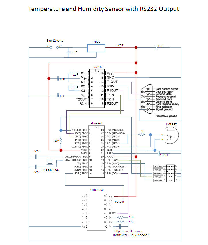
This is an affordable method for measuring temperature and humidity with a computer interface, designed as an entry-level project for high school students on a limited budget. The project involves the integration of a temperature and humidity sensor, such as...
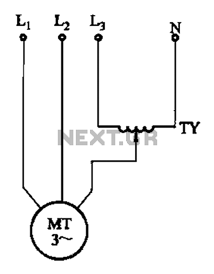
The circuit illustrated in Figure 3-175 features a regulator connected between one phase and neutral. It is designed for use with a 380V torque motor. This method offers advantages over the serious line imbalance approach, resulting in improved operating...
Control the state (on/off) and direction of two linear actuators that are essentially DC motors. The linear actuators operate at 12VDC and draw 10 amps of current at full load. A 25A external power supply has been purchased, as...
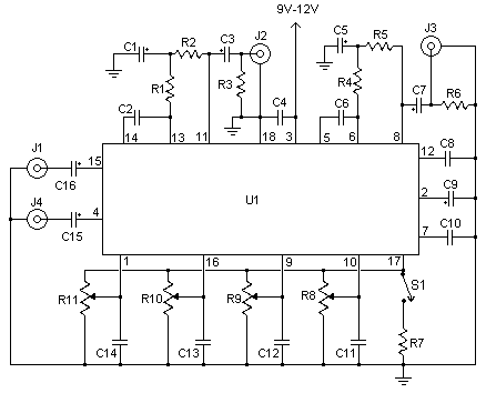
Tone Control. Parts: Total Quantity of Parts: Substitutions C1, C3, C5, C7, C15, C16 - 6 pieces of 2.2µF Electrolytic Capacitors; C2, C6 - 2 pieces of 0.05µF Ceramic Capacitors. The tone control circuit is designed to adjust the frequency...
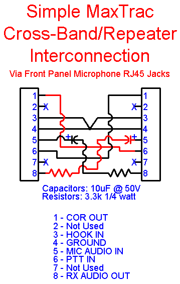
This article outlines a reliable, straightforward, and universal method for interfacing Motorola mobile radios from the MaxTrac, Radius, and GM300 series with common repeater controllers. The information provided is also relevant for radio interfaces used in IRLP or EchoLink...
Many applications require a large number of keys connected to a computing system. Examples include PC keyboards, cell phone keypads, and calculators. Connecting a single key to a microcontroller unit (MCU) is straightforward; however, connecting 10 or 100 keys...
Warning: include(partials/cookie-banner.php): Failed to open stream: Permission denied in /var/www/html/nextgr/view-circuit.php on line 713
Warning: include(): Failed opening 'partials/cookie-banner.php' for inclusion (include_path='.:/usr/share/php') in /var/www/html/nextgr/view-circuit.php on line 713