
Corridor counter delay circuit for controlling lights

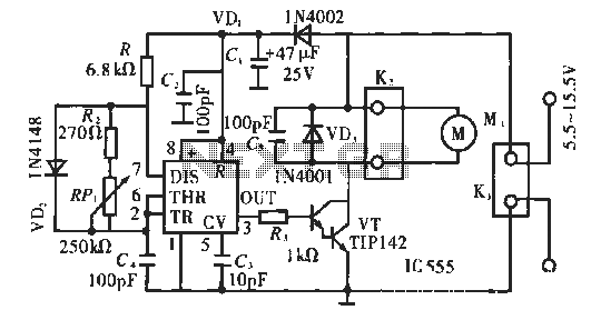
The corridor counter delay circuit is designed to manage lighting in corridor areas efficiently. The circuit utilizes a 555 timer configured in astable mode to generate a pulse-width modulation signal, which controls the timing of the relay operation. The CC40161 is a binary counter that keeps track of the number of oscillations produced by the 555 timer, allowing for the integration of time delays before activating the relay.
Upon energizing the circuit, the 555 timer initiates oscillation, producing a square wave output. This output is fed into the CC40161, which counts the pulses. The R3 and C5 components form an RC time constant that determines the integration time, effectively controlling how long the circuit will wait before responding to the count.
When the binary count reaches a predetermined value, the CC40161 activates the relay K. This relay has two sets of contacts: K-1, which is normally open, closes to power the lights (H), and K-2, which is normally closed, opens to disconnect the circuit from the power source, ensuring that the lights are only on for the required duration. The output of the CC40161 going high signals that the counting process is complete, allowing for a controlled and efficient lighting solution in corridor settings.
This design minimizes energy consumption by ensuring that lights are only activated when necessary, thus providing both functionality and efficiency in corridor lighting management.Corridor counter delay circuit for controlling lights This circuit is tested and functionable. When the circuit is energized, the 555 oscillator starts to oscillate, CC40161 is cleared R3, C5 integrating circuit composed of the state and into the count. Relay K to be energized, K-1 is closed, lights H lit, while K-2 normally closed contacts disconnect, C C40161 of E, goes high.
Related Circuits
This schematic illustrates a simple yet effective LED dimmer circuit utilizing the well-known voltage regulator IC LM317T. The LM317T can function as a current regulator, as demonstrated in this circuit. It features ten super bright white LEDs, although the...

This circuit is designed for precise centigrade temperature measurement. It features a transmitter section that converts the sensor's output voltage, which is proportional to the measured temperature, into frequency. The output frequency bursts are transmitted through the mains supply...
This heatsink temperature monitor circuit uses three LEDs to signal when the temperature exceeds two boundary levels. When the heatsink temperature is below 50-60°C (122-140°F), the green LED lights up. The yellow LED indicates that the temperature is between...
The circuit operates using pulse position modulation, which is a method distinct from the more commonly utilized pulse width modulation for speed control. A 555 timer is employed as a square wave modulator, generating output pulses with a fixed...
This circuit gradually switches the internal lights of a car on and off. The delay time can be adjusted by changing the values of the 10k and 4.7M resistors, as well as the capacitor. The circuit operates by utilizing a...
This circuit measures the distance covered during a walk. The hardware is housed in a small box that fits into a pocket, and the display operates as follows: the leftmost display, D2 (the most significant digit), shows distances from...