
Clock using a Hard Drive

More: Infrared Beam sensor and drilled index hole in lower drive platter. Three micro switches to set hours, minutes and seconds. Custom programmed PIC16F628 microcontroller to control clock operation. 1) Select Drive: Find an old hard drive that can spin up when power is connected, you may have to disconnect the 40 pin data cable to see that it can spin up. The drive must spin counter clockwise.
2) Open Drive: Open the drive and see that there are three platters in the unit. We will need three since the top one will have a slot cut into it, the second one will have a piece of white tape (or some other highly reflective material attached). And the third platter will have an index hole drilled into it, this index hole will be used to determine where the slot is when it is spinning. It could still work using a two platter drive but the top of the infrared beam sensor would be visible when a hand is over it.
3) Cut Slot: Remove the screw in the center of the platters, this should allow the platters to be removed. Cut a slot into the 1st platter, I clamped the platter into a vice protecting the surface with cardboard so it wouldn’t scratch. A grinder was then used to cut the groove. It was very easy to cut since it was made of aluminum. NOTE: The top platter that I ended up using was from a more modern drive. The older drive had platters that were dark brown and not very reflective, the modern drive had platters that had a silver mirror finish.
4) Drill index hole: Drill a ¼ inch hole near the edge of the 3rd platter. The infrared beam sensor will be positioned around this last platter so make sure that the index hole is in a location that will trip the beam. This optical beam sensor (also known as an optical interrupt switch) is made up of two separate electronic units combined in one housing. The sensor is in the shape of a horseshoe, an infrared LED is mounted in one half and a phototransistor is mounted in the other. The LED is always powered and emitting infrared light (invisible to the human eye). There are two distinct states that this type of device can detect. When there is no obstruction to the beam the phototransistor conducts allowing the circuit connected to it to sense that the beam is not broken. When the beam of infrared light is obstructed the phototransistor no longer conducts and the circuit will sense this also. This device works very well for the Hard Drive Clock since an index hole drilled in the lower platter is all that is needed to interface this device to the platter assembly. With this installed the PIC chip can detect the exact location of the rotating platters once per revolution.
5) Install the LEDs: Mark and drill holes in the outer case housing for LEDs, 12 in total, 6 blue and 6 red. More will give better hand visibility but 12 seems adequate. Make sure the LEDs are super bright type, standard LEDs will not be bright enough to cast a good beam. Drill all holes halfway between platters 1 and 2 (top and center). The LEDs can be installed using hot glue, ensuring they are aimed for the most effective angle during the drying time.
6) MOD the R/W Arm: Decide if the read/write arm assembly will remain in place. If not desired, remove it or cut the arms off to prevent interference with the spinning platter that has a slot cut into it.
7) Install Infrared Beam Sensor: The infrared beam sensor should be installed using hot glue in the lower right area of the drive. Its placement should ensure visibility of the index hole that was cut into the 3rd platter. If purchasing the sensor is not preferred, it can be salvaged from various old electronic items such as FAX machines or floppy drives.
Construct and Mount Circuit Board: A perf board can be used to create the circuit board, following the provided schematic diagram for construction. The board should be mounted securely to the hard drive, with connections made to the LEDs, infrared beam sensor, and the power input of the hard drive. The custom programmed PIC16F628 microcontroller will manage the clock’s operation, utilizing the micro switches for setting hours, minutes, and seconds. This project combines mechanical modifications with electronic components to create a unique timekeeping device.Have an old hard drive that no longer works? As long as it still spins up chances are you could build a clock out of your old hard drive! You will need some electronic knowledge, some common electronic components and a bit of patience. The clock that is produced isn’t exactly practical since most hard drives (especially older ones) are too loud for a clock that is to operate 24 hours a day. Uses 12 high power LEDs for displaying the clock hands, 6 Blue and 6 Red. Slot cut into upper drive platter and white tape on center drive platter provides a slot that when illuminated by the LEDs will represent a clock hand.
Minute hand is represented by blue light, hour hand is represented by red light and the second hand is represented by purple (both blue and red on at the same time). Infrared Beam sensor and drilled index hole in lower drive platter. Three micro switches to set hours, minutes and seconds. Custom programmed PIC16F628 microcontroller to control clock operation. 1) Select Drive: Find an old hard drive that can spin up when power is connected, you may have to disconnect the 40 pin data cable to see that it can spin up. The drive must spin counter clockwise. 2) Open Drive: Open the drive and see that there are three platters in the unit. We will need three since the top one will have a slot cut into it, the second one will have a piece of white tape (or some other highly reflective material attached.
And the third platter will have an index hole drilled into it, this index hole will be used to determine where the slot is when it is spinning. It could still work using a two platter drive but the top of the infrared beam sensor would be visible when a hand is over it.
3) Cut Slot: Remove the screw in the center of the platters, this should allow the platters to be removed. Cut a slot into the 1st platter, I clamped the platter into a vice protecting the surface with cardboard so it wouldn’t scratch.
A grinder was then used to cut the grove. It was very easy to cut since it was made of aluminum. NOTE: The top platter that I ended up using was from a more modern drive. The older drive had platters that were dark brown and not very reflective, the modern drive had platters that had a silver mirror finish. 4) Drill index hole: Drill a ¼ inch hole near the edge of the 3rd platter. The infrared beam sensor will be positioned around this last platter so make sure that the index hole is in a location that will trip the beam.
This optical beam sensor (also known as an optical interrupt switch) is made up of two separate electronic units combined in one housing. The sensor is in the shape of a horse shoe, an infrared LED is mounted in one half and a phototransistor is mounted in the other.
The LED is always powered and emitting infrared light (invisible to the human eye). There are two distinct states that this type of device can detect. When there is no obstruction to the beam the phototransistor conducts allowing the circuit connected to it to sense that the beam is not broken. When the beam of infrared light is obstructed the phototransistor no longer conducts and the circuit will sense this also.
This device works very well for the Hard Drive Clock since an index hole drilled in the lower platter is all that is needed to interface this device to the platter assembly. With this installed the PIC chip can detect the exact location of the rotating platters once per revolution.
5) Install the LEDs: Mark and drill holes in the outer case housing for LEDs, I used 12 in total, 6 blue and 6 red. More will give better hand visibility but 12 seems adequate. Make sure the LEDs are super bright type, standard LEDs will not be bright enough to cast a good beam.
Drill all holes half way between platters 1 and 2 (top and center). I installed them using hot glue, the glue takes a while to dry, during the drying time I temporarily power them and aimed them for the most effective angle. 6) MOD the R/W Arm: Decide if you want the read write arm assembly in place. Remove it if not desired or cut the arms off so they don’t interfere with the spinning platter with a slot cut into it.
7) Install Infrared Beam Sensor: To install this I used some hot glue and placed it in the lower right area of the drive. Placement does not matter as long as it can see” the index hole that was cut into the 3rd platter. If you don’t want to purchase this sensor it can be taken out of a variety of old electronic items such as old FAX machines, floppy drives, VCR’s.
Chances you have something lying around that has just what you are looking for. The one I used came out of an old 51/4 inch floppy drive. Construct and Mount Circuit Board: Use some perf board to create the circuit board, there is a schematic diagram below to show you how to construct it. Find some way to mount the board to the hard drive. I mounted the circuit board to a piece of plastic which was screwed to the back of the hard drive. Connect the wires from the circuit board to the LEDs, infrared beam sensor and the hard drive power input.
🔗 External reference
Related Circuits
This circuit is designed for children's entertainment and can be installed on bicycles, battery-powered cars, motorcycles, as well as on models and various games and toys. When switch SW1 is positioned as depicted in the circuit diagram, it generates...
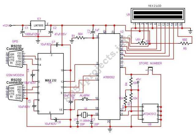
In this project AT89S52 microcontroller is used for interfacing to various hardware peripherals. The current design is an embedded application, which will continuously monitor a moving Vehicle and report the status of the Vehicle on demand. For doing so...
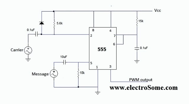
The 555 integrated circuit (IC) is configured in monostable mode of operation. In this mode, the output remains LOW (0V) when there is no trigger input. When a trigger is applied through pin 2, the output switches to HIGH...
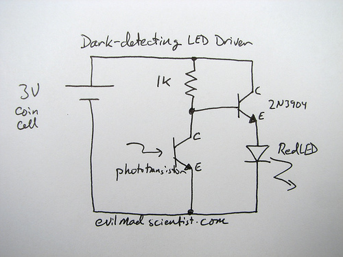
A circuit that uses a phototransistor to create a light-sensitive switch. When there is no light in the room, the LED connected to the phototransistor lights up, and when there is light, the LED turns off. Any schematic or...
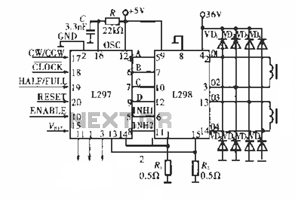
The circuit operates using a dedicated stepping motor controller, the L297. Pin 17 (CW/CCW) is utilized to control the rotation direction of the stepper motor. Pin 18 (CLOCK) regulates the speed of the stepper motor, while pin 19 (HALF/FULL)...
This is a programmable clock timer circuit that utilizes individual LEDs to indicate hours and minutes. Twelve LEDs can be arranged in a circle to represent the 12 hours of a clock face, and an additional 12 LEDs can...