
Zhichuan Electronic Circuit
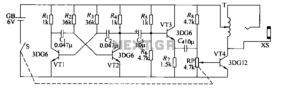
The electronic anti-asthmatic device is designed to provide high-voltage stimulation pulses as a supplementary treatment for cough-related conditions. The self-excited multivibrator serves as the core oscillator, producing a square wave signal at a frequency of approximately 500 Hz. This frequency is crucial for the efficacy of the treatment, as it is within a range that is thought to stimulate the respiratory system effectively.
The circuit utilizes two transistors, VT1 and VT2, configured in a feedback loop that allows for continuous oscillation. Capacitors C1 and C2 play a pivotal role in determining the timing and stability of the oscillation, while resistors R1 and R2 set the biasing conditions for the transistors. The output from the multivibrator is fed into a buffer amplifier, which isolates the oscillation circuit from the high-voltage components, ensuring that the oscillation signal remains stable while providing sufficient drive to the subsequent amplification stages.
The buffer amplifier, utilizing the emitter follower configuration with VT3, ensures that the voltage level remains consistent and can drive the high-voltage generation circuit. The coupling capacitor C4 prevents any DC offset from affecting the high-voltage output.
The high-voltage generation circuit is critical for the operation of the device. The potentiometer RP allows for fine-tuning of the output voltage, while resistor RS helps in controlling the current flowing through the output stage. The amplification tube VT4 significantly boosts the voltage level, which is then stepped up further by the transformer T. This transformer is designed to handle the high-frequency oscillations, converting them into high-voltage pulses suitable for therapeutic applications.
The final output is delivered through output jacks XS, which connect to external electrode sheets. These sheets are strategically placed on the patient's body at specific acupuncture points, such as the sternum and cervical spine, to maximize the therapeutic effect. The adjustment of the potentiometer RP and the resistance RI enables the operator to customize the intensity of the electric pulse, tailoring the treatment to the patient's needs. This flexibility is essential for ensuring patient comfort and optimizing therapeutic outcomes.The saying goes "dead ringworm surgical, medical dead asthma." This example describes an electronic anti-asthmatic, high voltage stimulation pulse it produces, to cough patients can play a role of adjuvant therapy. (1) circuit Zhichuan circuit by the self-excited multivibrator, the buffer amplifier and high voltage generating circuit, shown in Figure 24-2. Self-excited multivibrator transistors VT1, VT2, capacitors c1, c2, and a resistor R. -R. And other components. Buffer amplifier circuit by the emitter follower amplifier tubes VT3, wind bias resistor, R. And a coupling capacitor C, C4 composition. High voltage generation circuit by the potentiometer RP, resistor Rs, amplified output tube VT4, auto-type step-up transformer T and output jacks acne XS components.
(2) works self-excited multivibrator generates a frequency of the oscillation signal of about 500Hz, the VT3, VT4 amplification and transformer T boost after treatment, from the socket at the output is greater than xS iocf , 1 high-voltage pulse voltage. The pulse voltage by two external electrode sheet was added to cough patient days sudden hole (riding his head, in the chest on the edge of the middle notch accounting depression) and too vertebral points (commission conical cap or sitting down in the first 7 cervical spine), adjust the positioner RI resistance, can change the output voltage of the high-voltage pulse amplitude, to adjust the intensity of the electric pulse.
Related Circuits
Hello everyone. This is my first post in quite some time. I obviously do not have an old enough catalog for reference. In the data section, there were references to... The input data indicates a lack of sufficient information regarding...
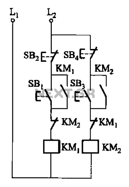
A, B, and two electric motors allow simultaneous operation through interlock control. The two motors can be connected in series with each other using normally closed contacts in the respective coil circuit. The circuit design facilitates the interlocking operation of...
Circuit designed to alleviate concerns related to high frequency utilizes a ready-made module, specifically an Aurel audio FM transmitter. This compact circuit board, measuring 2 cm by 4 cm, supports a modulation frequency track and delivers an RF power...
This 555 timer circuit toggles a relay when a button is pressed. Pins 2 and 6, which are the threshold and trigger inputs, are maintained at half the supply voltage by two 10K resistors. When the output is high,...
The following circuit illustrates a fully linear diode sensor circuit diagram. This circuit is based on the A748 integrated circuit (IC). Features include the use of an operational amplifier (op-amp). The fully linear diode sensor circuit utilizes the A748 IC...
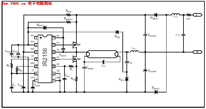
The IR2156 provides a cost-effective solution for fluorescent electronic ballasts. It integrates features such as lighting tube error protection and a programmable working frequency, which includes warm-up, lighting, and continuous operation of the ballast. The IR2156 is a highly integrated...
Warning: include(partials/cookie-banner.php): Failed to open stream: Permission denied in /var/www/html/nextgr/view-circuit.php on line 713
Warning: include(): Failed opening 'partials/cookie-banner.php' for inclusion (include_path='.:/usr/share/php') in /var/www/html/nextgr/view-circuit.php on line 713