
RF-powered sidetone oscillator
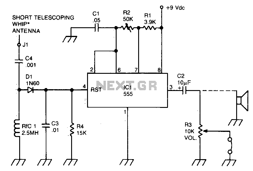
The sidetone oscillator circuit typically incorporates a 555 timer IC configured in an astable mode, allowing it to generate a continuous square wave output. This output can be modulated by the RF signal received from a transmitter, which serves to turn the oscillator on and off. The keying mechanism is facilitated by applying a positive DC voltage to the reset pin of the 555 timer, effectively interrupting the oscillation when required.
In terms of design, the circuit consists of several key components: the 555 timer IC, resistors, capacitors, and a power supply. The resistors control the charge and discharge times of the timing capacitor, thus determining the frequency of the output waveform. The capacitor, in conjunction with the resistors, sets the oscillation frequency, which is crucial for the sidetone audio signal.
The RF signal is coupled to the reset terminal of the 555 timer, allowing the oscillator to be synchronized with the transmitter's operation. This ensures that the sidetone audio is generated only when the transmitter is active, providing an audible feedback to the operator. The battery power source ensures portability and ease of use in various field applications.
In summary, the sidetone oscillator serves as an essential component in communication systems, providing audio feedback during transmission while being efficient and compact due to the use of the 555 timer IC. Proper design and component selection are critical for achieving the desired performance characteristics in specific applications.A sidetone oscillator is a special audio astable multivibrator. Keying is accomplished oscillator that is turned on and off with the by applying a positive dc potential, developed transmitter. The oscillator is rf-driven and bat- from the rf signal, to the reset terminal of the tery operated It uses a 555 IC timer as an 555. 🔗 External reference
Related Circuits
A voltage-controlled oscillator is an oscillator whose frequency of oscillation can be varied by changing an applied voltage. A voltage-controlled oscillator (VCO) is an essential component in various electronic systems, particularly in communication devices, signal processing, and modulation applications. The...
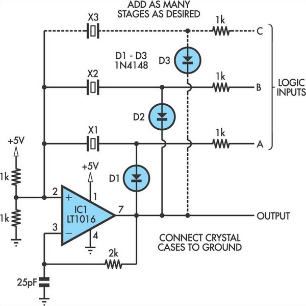
This oscillator circuit allows crystals to be electronically switched through logic commands. The circuit is best comprehended by initially disregarding all crystal components. The oscillator circuit described functions as a frequency generator that utilizes the properties of quartz crystals to...

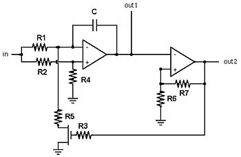
This circuit generates sine and square wave signals with frequencies ranging from below 20 Hz to above 20 kHz. The advantage of this circuit diagram is that the output frequency can be adjusted by varying the variable resistor R6. The...
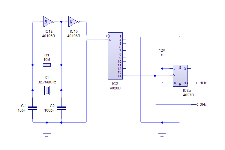
This plugin utilizes a quartz oscillator featuring a crystal (X1) to produce a 32,768 Hz (32,768 = 2^15) output. This frequency is fed into a 4020 14-Stage Ripple Counter, which divides the signal by 2^14, resulting in a 2...
An op-amp based Colpitts oscillator in Multisim displays a "timestep too small" error when the run button is pressed. Despite extensive research and attempts to resolve the issue, the error persists. The design features a C-L-C pi circuit that...
These are resonant circuits or tank circuit oscillators. They are commonly used to produce high frequencies ranging from 1 MHz to 500 MHz; hence, they are also known as RF oscillators. These oscillators are utilized in RF generators, radio...