
LC feedback Oscillator

The Hartley oscillator circuit exemplifies a fundamental RF oscillator configuration, facilitating the generation of high-frequency signals essential for various applications in communication systems. The inductively coupled coils, L1 and L2, enable the oscillator to operate efficiently across a wide frequency range, making it suitable for local oscillation in radio receivers. The RFC plays a critical role in ensuring that the oscillator maintains its operational integrity by allowing DC current flow while blocking AC signals, thus preserving the necessary conditions for oscillation.
The feedback mechanism, achieved through the autotransformer action, is crucial for sustaining oscillations. The 180-degree phase shift introduced by the coils, combined with the additional phase shift from the transistor, ensures that the feedback is constructive, allowing for consistent signal amplification. The capacitors Cc and CB are vital components that prevent DC current from interfering with the AC operation, thereby stabilizing the oscillation process.
In contrast, the Colpitts oscillator, utilizing capacitors for feedback instead of inductors, showcases versatility in oscillator design. The interaction between capacitors C1 and C2 and the coil L establishes a similar feedback mechanism, maintaining the oscillator's performance across the specified frequency range. The design considerations, such as the choice of components and the configuration of the circuit, directly influence the oscillator's frequency stability and output amplitude.
Overall, these oscillators are integral to modern electronic communication systems, providing reliable high-frequency signals necessary for efficient signal transmission and reception. The principles governing their operation are foundational in the field of electronics, emphasizing the importance of feedback mechanisms and component selection in oscillator design.These are resonant circuit or tank circuit oscillators. They are commonly use to produced high frequencies as ranging from I MHz to 500 MHz Hence they are also known as RF oscillators. These oscillators are used in RF generators, radio transmitters and receivers. Some popular IC feedback oscillators are of the following types. Hartley oscillator i s very popular and is commonly used as a local oscillator in radio receivers. The main advantages of this oscillator is wide range of frequencies and easy to use. Figure shows the circuit of Hartley oscillator. Its tank circuit consists of two coils L1 and L2. The coil L1 is inductively coupled to coil L2 and the combination works as an auto transformer. A coil called radio frequency choke RFC is connected between the collector and the Vcc supply. It acts as load for the collector and also permits an early flow of D. C current but blocks AC current. The feedback between the output and input circuit is accomplished, through auto transformer actions which also introduces a phase shift of 180o. The phase reversal between the output and input voltage occurs because they are taken from the opposite end of the coil L1 and L2 with respect to the tap, which is grounded.
It may be observed that the tap on the combination L1 and L2 coils is actually connected to the transistor emitter terminal via ground and through the capacitor CE. As the transistor also introduces a phase shill of 180 °, therefore the total phase shift is 360 ° and hence the feedback is positive.
As the capacitor Cc connected between the collector and the tuned circuit permits only the A. C currents to pass to the tank circuit. It means capacitor Cc blocks the D. C current. The capacitor CB is called blocking capacitor it further blocks the D. C current from reaching to the base. The resistors R1, R2 and RE are used to provide D. C bias to the transistor. The colpitts oscillator is widely used in commercial signal generators from frequencies between 1 MHz and 500 MHz. It is similar to the Hartley oscillator with minor modifications. Instead of using a tapped inductance, two capacitors are tapped as shown in Figure. The frequency of oscillations if mutual inductance ignored is given by the relation As the points A and B are 180 ° out of phase with each other.
Also another phase shift of 180 ° is provided by the transistor itself hence there is a total phase shift of 360 °between the emitter-base and collector-base circuits. When the supply is ON, the capacitors C1 and C2 are charged. These capacitors discharge through the coil L, which set up the feedback to the base-emitter junction and obtain in an amplified form at the collector of the transistor.
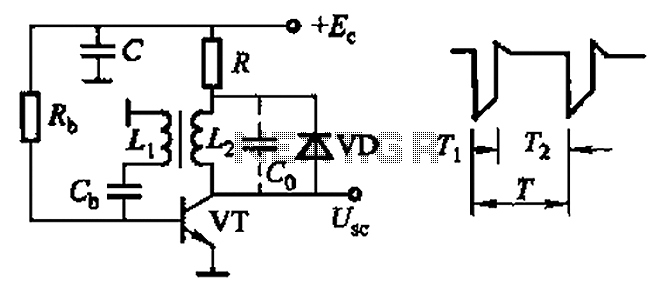
Due to the positive feedback, the oscillation of constant amplitude is obtained. A tuned collector oscillator circuit using a transformer is shown in Figure. The primary of the transformer forms a tuned circuit with capacitor C and it decides the frequency of oscillation. Its amplifier provides a phase difference of 180 ° and an additional phase difference of 180 ° is provided by the transformer, it will result in positive feedback.
For the oscillatory action, the transistor amplifier provides sufficient gain. The resistors R1, R2 and RE provide D. C bias to the transistor. CE and C2 are bypass capacitors, so that resistors RE and R2 have no effect on A. C operation. The D. C bias is provided by the resistors R1 and R2 through the low-resistance secondary winding which also provides A. C feedback. The output of the tuned collector oscillator is taken by using transformer coupling. The output terminals are connected to the power consuming device or input terminals of the next stage.
This loads the tank circuit and its effective dissipative resistance increases and circuit losses are increased. To maintain oscillations, more positive feedback is required which is achieved by increasing coupling of the transformer.
The 🔗 External reference
Related Circuits
This Hartley oscillator was constructed using a single 45 tube and is based on a design published in a 1932 QST article by George Grammer. The initial circuit experienced performance issues due to weak 45 tubes, necessitating a very...
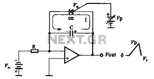
A sawtooth voltage-controlled oscillator operates by first generating a negative potential maximum at the output of the comparator. This output is then fed to the inverting input terminal through resistor R1, which is part of the relaxation oscillator. The...
Millimeter-wave frequency bands are appealing due to their wide available bandwidths. Signals can be generated in various ways; however, for each type of oscillator, electronic tuning of the source in a defined and controlled manner is desirable. Employing a...
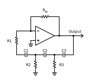
Phase-shift oscillator. An oscillator in which a network has a phase shift of 180 degrees. A phase-shift oscillator is a type of electronic oscillator that generates a sinusoidal output signal. It typically consists of an amplifier and a phase-shifting network...
Common non-sinusoidal oscillator circuit, waveform and frequency formula - sawtooth oscillator - use blocking oscillator The sawtooth oscillator is a type of non-sinusoidal oscillator that generates a waveform characterized by a linear rise in voltage followed by a rapid drop....
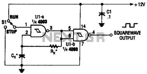
Two gates of the Quad 4093 are utilized to create an oscillator. The resistor (R) can range from approximately 5 kΩ to around 10 kΩ. The capacitor (Cx) can vary from about 10 pF to higher values, with the...