
Simple Adjustable Sine/Square Wave Oscillator Circuit schematic with explanation

The circuit primarily consists of an oscillator configuration capable of producing both sine and square wave outputs. The frequency of oscillation is determined by the components involved, particularly the variable resistor R6, which allows for fine-tuning of the frequency output.
The oscillator can be built using operational amplifiers or dedicated waveform generator ICs. In a typical configuration, the output from the oscillator is fed into a waveform shaping stage to produce a clean sine wave output. This stage may include filtering components such as capacitors and resistors that smooth the output signal, reducing harmonics and noise.
For the square wave output, the circuit may utilize a comparator or a Schmitt trigger configuration that converts the sine wave into a square wave. This conversion is crucial for applications requiring digital signal processing or timing applications.
The circuit's frequency range, extending from below 20 Hz to above 20 kHz, makes it suitable for various applications, including audio signal generation, testing of audio equipment, and educational demonstrations in electronics courses. The ability to adjust the frequency using R6 provides flexibility for users to set the desired frequency for their specific application.
Power supply considerations for the circuit should also be noted. A stable DC supply is essential for consistent performance, and bypass capacitors may be added to the power supply lines to filter out any noise that could affect the oscillator's operation.
Overall, this circuit serves as a versatile tool for generating sine and square wave signals across a wide frequency spectrum, making it an essential component in many electronic applications.This circuit provides sine and square wave at frequency of below 20Hz up to above 20KHz. The benefit of this circuit diagram is that you can adjust the output frequency by varry the variable resistor of R6. 🔗 External reference
Related Circuits
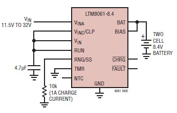
A simple and efficient lithium battery charger and monitoring system can be designed using the LTM8061 integrated circuit from Linear Technology. The LTM8061 is a high-efficiency 32V, 2A module standalone lithium battery charger optimized for one- and two-cell packs,...
The first reverberator presented is based on the TDA1022, which is the most commonly used BBD (Bucket Brigade Device). Adjustments for proper functionality of the reverberator are required before connecting the power supply. The TDA1022 is a versatile BBD that...
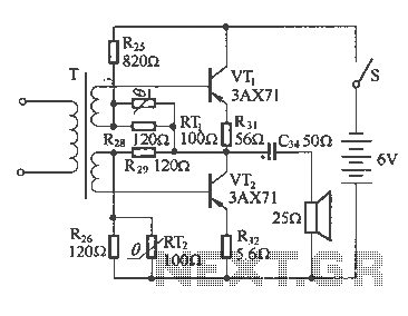
The following diagram illustrates a common output transformerless (OTL) amplifier circuit that delivers an output power of 100 mW. The circuit includes an output transformer and a capacitor, which work in conjunction with speaker units. The frequency characteristics of...
The Armstrong oscillator is utilized to generate a sine-wave output with a constant amplitude and fairly stable frequency within the RF range. It is commonly employed as a local oscillator in receivers, as a source in signal generators, and...
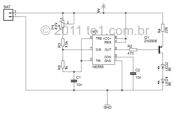
This small device is designed to jam remote controls by directing it at the TV. The circuit utilizes a 555 timer configured as an astable multivibrator, generating a frequency of approximately 38 kHz, which corresponds to the frequency at...
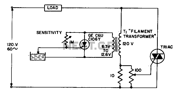
The circuit supplies power to the load until water conducts through the probe, allowing gate current to bypass from the low current SCR. This configuration provides an isolated low voltage probe to meet safety requirements. The described circuit operates as...