
Rf Preamplifiers Circuit
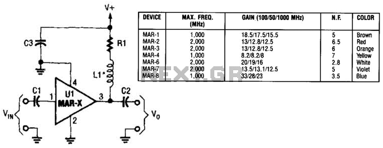
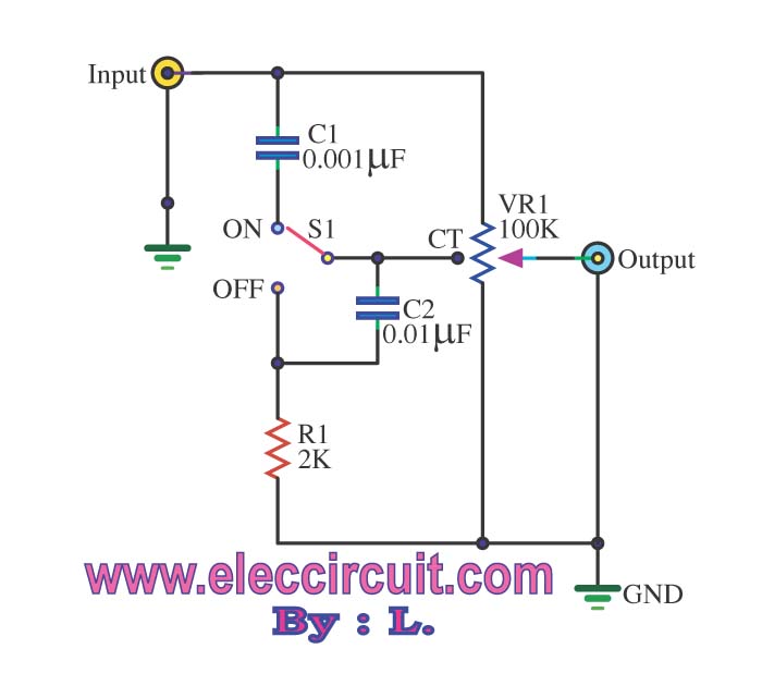
The MAR-x circuit configuration utilizes two crucial DC-blocking capacitors, C1 and C2, which serve to prevent any DC voltage from affecting the subsequent stages of the circuit while allowing AC signals to pass. The input capacitor, C1, is positioned at the input stage to filter out any DC components present in the incoming signal, ensuring that only the desired AC signal is processed by the MAR-x device. Similarly, the output capacitor, C2, performs the same function at the output stage, allowing for the clean transmission of the AC signal to the next stage of the circuit without any DC offset.
The power supply network, consisting of an inductor (L1) and a resistor (R1), plays a critical role in providing the necessary DC voltage and current to the MAR-x. The inductor L1 is typically chosen to provide a stable current supply while minimizing any potential ripple that could affect performance. The resistor R1 may be used for current limiting or to provide a specific load to the circuit, ensuring that the MAR-x operates within its specified parameters.
The connection of the power supply network to the MAR-x via the RF output terminal (lead 3) is essential for proper operation. This connection allows the MAR-x to receive the necessary power while also facilitating the transfer of the RF signal, which is critical for the overall functionality of the circuit. Proper attention must be given to the layout and component selection to ensure optimal performance and reliability of the MAR-x circuit. In this basic MAR-x-based circuit, both the input and output are comprised of a single dc-blocking capacitor (CI and C2 for the input and output, respectively). The dc power-supply network (comprised of LI and Rl) is attached to the MAR-x via the RF-output terminal (lead 3). 🔗 External reference
Related Circuits
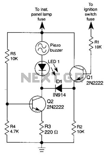
The base of Q1 is connected to the car's ignition circuit; the easiest point to make that connection is at the ignition switch fuse in the car's fuse panel. Also, one side of the piezoelectric buzzer is connected to...
The SC41343 is designed as a type of infrared, ultrasonic, or RF remote control launch coding circuit. The internal circuit comprises a sequence generator, control logic circuit, 4-bit shift register, data extraction circuit, and latch circuit. Features include the...
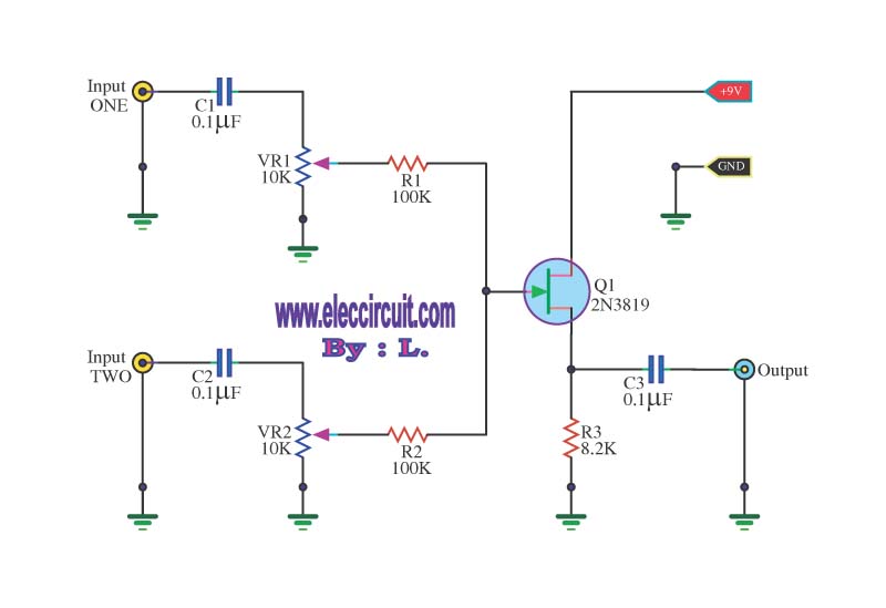
This circuit is a simple mixer circuit that can mix two signal channels into one output channel. It utilizes a codec circuit to convert stereo audio into mono audio. The circuit can also increase the number of channels by...
The passive tone control circuit is designed to adjust the bass without expansion, utilizing resistors (R) and capacitors (C). It functions as a frequency filter and is easy to construct, requiring no external power supply. This circuit can be...
The EUA2032 is a high-efficiency, 2.5W mono class-D audio power amplifier. A newly developed filterless PWM modulation architecture further reduces EMI and THD+N, as well as eliminates the LC output filter, thereby reducing the external component count, system cost,...
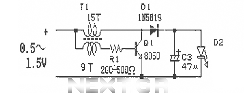
This is a simple and easy-to-build DC-DC driver circuit designed for a single flashlight battery, operating at a parametric voltage of 1.5V. The input current is 90mA, while the light-emitting diode (LED) current is 26mA or higher. The circuit...