
Simple audio mixer circuit with fet 2n3819
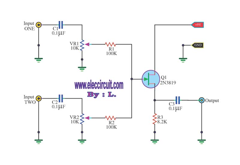
This simple mixer circuit is designed to efficiently combine two audio signal channels into a single output, making it ideal for applications where space and power consumption are critical. The use of a codec circuit is instrumental in converting stereo audio to mono, ensuring compatibility with various audio systems that may only support mono inputs.
The addition of variable resistors VR1 and VR2 allows for fine-tuning of the audio levels from each input channel, providing flexibility in mixing. Resistors R1 and capacitor C1 can be adjusted to modify the circuit's response to different audio sources, enabling customization based on user requirements or specific application needs.
The low current consumption characteristic of this circuit makes it particularly advantageous for portable applications, as it can operate effectively on a 9-volt battery, extending the operational life of the device.
The audio signal path begins with the incoming voice signals at either input 1 or input 2. These signals are coupled through capacitors C1 and C2, which isolate the DC components and allow only the AC audio signals to pass through. The signals then reach the variable resistors for adjustment, after which they are processed by the FET Q1. This FET serves as an amplifier, enhancing the audio signal before it is sent to the output stage.
Finally, the output pin S transmits the mixed audio signal, which is again coupled through capacitor C3. This final coupling stage ensures that any DC offset is removed, delivering a clean audio signal to subsequent stages or devices. Overall, this circuit provides a compact and efficient solution for audio mixing applications.This circuit, a simple mixer circuit. It can mix two signal channels and one channel is output. Using a codec circuit, Convert stereo audio to mono audio time. It can increase the number of channels too. By adding a VR1, R1 and C1 to the amount needed. Then connected to Buffett a new one. Most importantly is eating circuit current is very low. Can use with 9-volt batteries immediately. When entering voice signal, one of input 1 and input 2. Audio is via C1 and C2 of each channel, served coupling signals to VR1 and VR2. To adjust the audio to the Fet Q1. Which it serves, including audio. Then expand signal the output pin S through C3 For coupling signal again, before leaving to the output. 🔗 External reference
Related Circuits
This application note describes the evaluation board for the AD7892-2, a 12-bit analog-to-digital (A/D) converter. The AD7892-2 is a high-speed, low-power device capable of 500 ksps sampling rate, operating from a single +5V supply. It features an on-chip track/hold...

Figure 1 illustrates an economical and straightforward Gate Alarm designed to operate using a small universal AC-DC power supply. IC1a functions as a fast oscillator, while IC1b serves as a slow oscillator. These two oscillators are integrated through IC1c...
Assistance is needed for a project involving the construction of a switch panel. The individual has a good understanding of 12V electrical wiring but is encountering difficulties with this specific task. The project involves designing a switch panel that can...
Due to the recent launch of Cranial Electrotherapy Stimulation (CES) portable devices in Europe, a similar circuit has been designed for hobbyists. CES is a widely used method for electrically enhancing brain function and has been prescribed by medical...
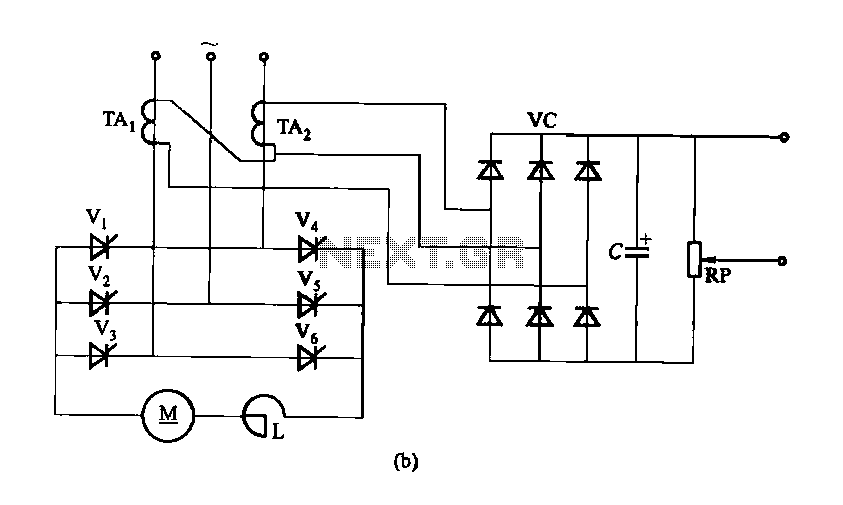
Figure 16-40 illustrates a three-phase rectifier circuit featuring a current cutoff feedback mechanism. In part (a) of the figure, three current transformers are utilized, while part (b) shows the configuration using two current transformers connected in an open delta...
The Ultra Fast Battery Charger for Nickel-Cadmium (NiCad) battery cells is designed to efficiently charge NiCad batteries. This charger, referred to as the Ultra Fast NiCad Battery Charger, is capable of rapidly filling NiCad battery cells. The charger is...