
rf probe circuit
RF Probe Circuits are essential tools for testing and analyzing radio frequency signals in various applications, including telecommunications, broadcasting, and electronic testing. These circuits allow engineers and technicians to measure the strength and quality of RF signals, making them invaluable for troubleshooting and development purposes.
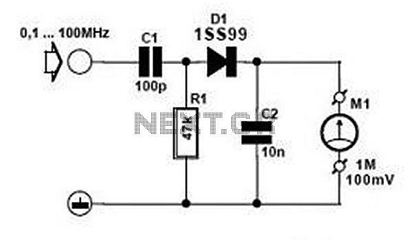
Typically, an RF probe circuit consists of a few key components: an antenna or coupling device for signal reception, an amplifier to boost the signal strength, and a detection circuit to convert the RF signal into a readable format. The design may also include filters to eliminate unwanted frequencies and improve measurement accuracy.
The antenna can be a simple wire or a more sophisticated design depending on the frequency range of interest. The amplifier is usually a low-noise amplifier (LNA) to ensure that the signal integrity is maintained during processing. The detection circuit may employ a diode or a specialized RF detector IC to convert the RF signal into a DC voltage that can be easily measured on a multimeter or oscilloscope.
When designing an RF probe circuit, considerations such as impedance matching, bandwidth, and noise performance are critical for achieving accurate measurements. Proper layout and grounding techniques are also essential to minimize interference and ensure reliable operation.
Users can find numerous resources online, including schematics, component lists, and assembly instructions, to build their own RF Probe Circuits. These resources often include detailed explanations of each component's role and the overall function of the circuit, providing a comprehensive understanding of RF measurement techniques.Good information about RF Probe Circuit. You can learn and download RF Probe Circuit online.. 🔗 External reference
Related Circuits
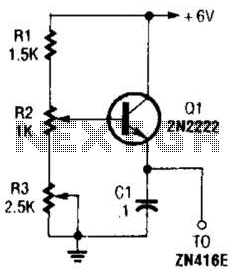
This regulator can be used with a +6-V source to supply the ZN416E low-voltage TRF radio receiver IC with the necessary +1.5 V. R3 sets the output voltage. The circuit utilizes a voltage regulator designed to convert a +6 V...
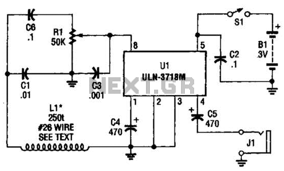
The VLF whistler receiver is designed to detect natural radio noise and signals that occur below 20 kHz. LI is a large loop antenna consisting of 250 to 300 turns of #26 gauge wire wound on a form with...
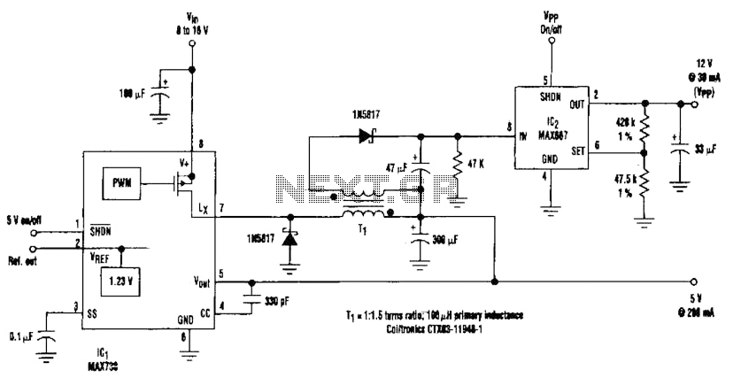
By adding a flyback winding to a buck-regulator switching converter, which functions as a 5-V supply with a 200-mA output capability, a 12-V output can be generated. The flyback winding on the main inductor, forming transformer T1, allows for...
The circuit employs two Light Dependent Resistors (LDRs) arranged in series with a separation of approximately half a meter. This configuration allows each LDR to detect the presence of a person entering or exiting the room. The processed outputs...
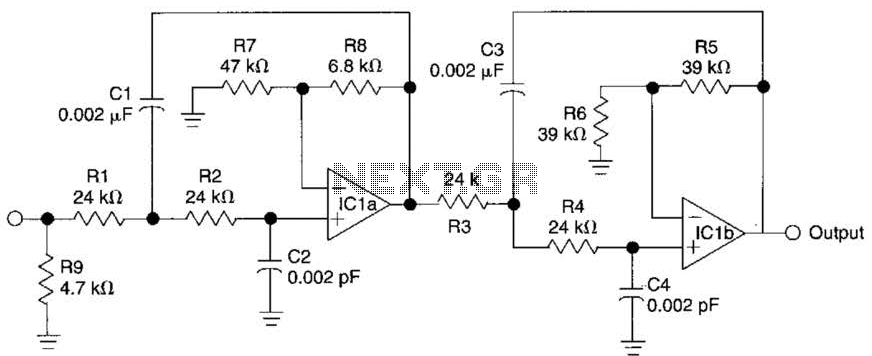
This circuit is a fourth-order low-pass filter designed for operation at kilohertz frequencies. The component values for resistors R1, R2, and capacitors C1, C2, as well as resistors R3, R4 and capacitors C3, C4 can be adjusted for functionality...
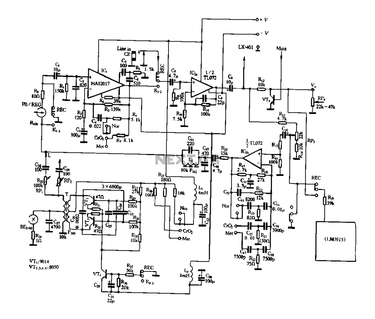
Figure 3-17 illustrates a pre-equalizer amplifier with sound recording capabilities, featuring the following characteristics: (1) The circuit does not utilize a conventional mechanical switch circuit; instead, it employs fully enclosed electromagnetic relays. This design allows for a core and...
Warning: include(partials/cookie-banner.php): Failed to open stream: Permission denied in /var/www/html/nextgr/view-circuit.php on line 713
Warning: include(): Failed opening 'partials/cookie-banner.php' for inclusion (include_path='.:/usr/share/php') in /var/www/html/nextgr/view-circuit.php on line 713