
Vlf Whistler Receiver Circuit
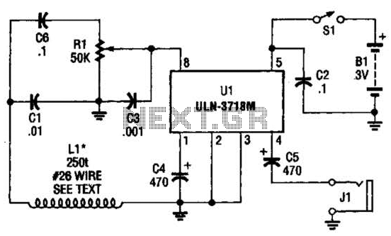
The VLF (Very Low Frequency) whistler receiver operates within the frequency range below 20 kHz, primarily capturing natural electromagnetic emissions from lightning strikes and other atmospheric phenomena. The primary component of this receiver is the large loop antenna, designated as LI. This antenna is constructed using 250 to 300 turns of #26 gauge wire, which provides a balance between sensitivity and bandwidth. The choice of wire gauge is crucial as it affects the antenna's resistance and overall efficiency.
The antenna is mounted on a form with a diameter of 3 feet, which is optimal for capturing low-frequency signals. The loop design enhances the magnetic field interaction with incoming radio waves, thus improving the receiver's ability to detect faint signals. It is essential that the antenna is installed away from power lines to reduce electromagnetic interference, which can significantly degrade the quality of the received signals.
Proper orientation of the antenna is also vital. By aligning the loop to minimize pickup from 60 Hz and 120 Hz power line frequencies, the receiver can focus on capturing the desired VLF signals. This orientation is typically achieved by adjusting the loop's position relative to known sources of electrical noise, ensuring that the primary signals of interest are not masked by unwanted interference.
In summary, the VLF whistler receiver, with its carefully designed loop antenna, is an effective tool for exploring natural radio phenomena, provided that installation considerations regarding distance from power lines and antenna orientation are meticulously followed. The VLF whistler receiver is intended to listen to natural radio noise and signals that occur below 20 kHz. LI is a large loop antenna that is 250 to 300 turns #26 gauge wire on a form 3` diameter. LI should be mounted well away from power lines and is oriented for minimum 60- and 120-Hz pickup. 🔗 External reference
Related Circuits
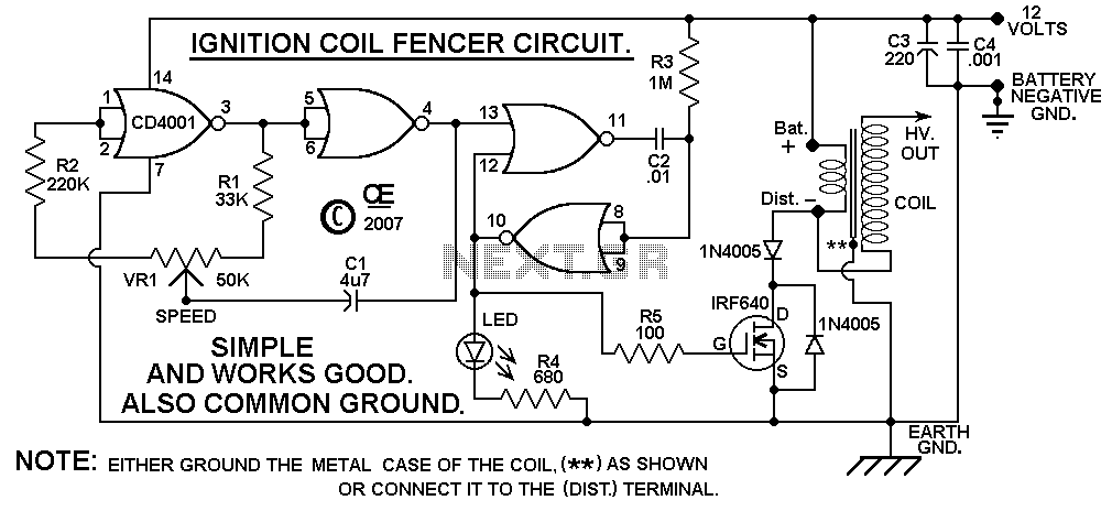
A circuit design based on a C-MOS chip to drive a car ignition coil. This is a very simple and efficient design for an electric fence. It puts out a very high voltage current pulse, yet it draws a...

The use of a differential capacitor enables temperature compensation in an LC circuit utilizing an NFO and N1500 ceramic. C6 serves as a differential capacitor featuring two stators and one common rotor. When one stator's capacitance reaches its maximum...
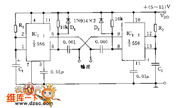
The circuit consists of two synchronized multivibrators formed by a pair of 555 timer circuits. It is capable of generating two synchronized pulse signals, with the spacing and frequency adjustable by modifying the time constant. The circuit offers flexibility...
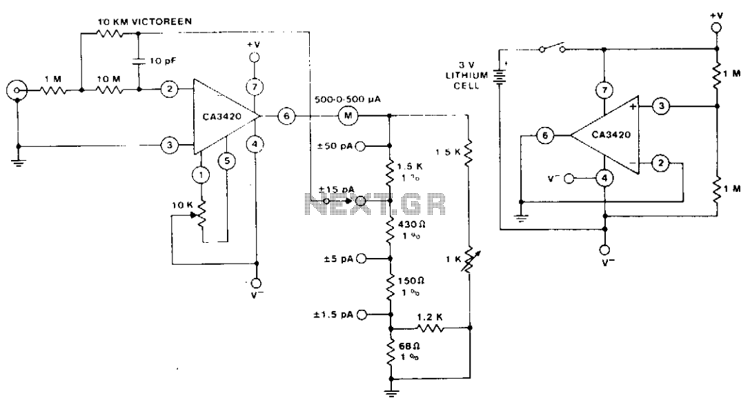
The circuit utilizes the extremely low input current (0.1 pA) of the CA3420 BiMOS operational amplifier. With only one 10 megohm resistor, it achieves a range from ±50 pA maximum to a full-scale sensitivity of ±1.5 pA. Additionally, by...
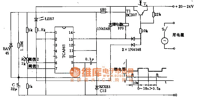
The foot 13 between valve value 1 and valve value 2 will draw the transistor base current. If the relay releases, after a recovery time of 0.5 seconds, pressing the key will initiate the switching process again. The timer...
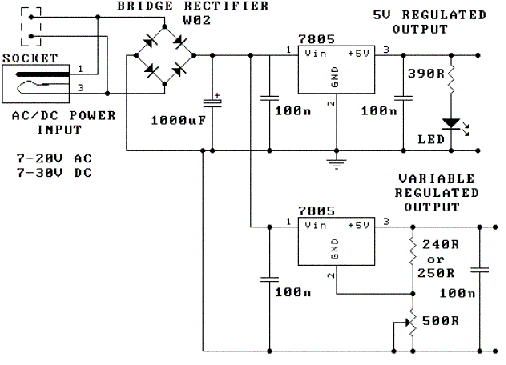
The following circuit illustrates how to build a variable DC power supply circuit. This circuit is based on the 7805 IC. Features: other output is ... The variable DC power supply circuit utilizing the 7805 integrated circuit (IC) is designed...
Warning: include(partials/cookie-banner.php): Failed to open stream: Permission denied in /var/www/html/nextgr/view-circuit.php on line 713
Warning: include(): Failed opening 'partials/cookie-banner.php' for inclusion (include_path='.:/usr/share/php') in /var/www/html/nextgr/view-circuit.php on line 713