
+1.5V Supply For Zn416E circuits
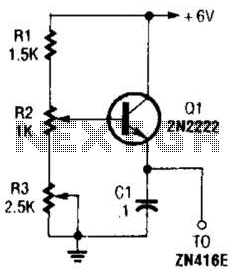
The circuit utilizes a voltage regulator designed to convert a +6 V input into a stable +1.5 V output, specifically tailored for powering the ZN416E low-voltage TRF radio receiver integrated circuit (IC). The regulator's primary function is to ensure that the ZN416E receives a consistent voltage level, which is crucial for its operation and performance in radio frequency applications.
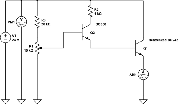
In this configuration, R3 plays a pivotal role in determining the output voltage level. By adjusting the resistance value of R3, the output voltage can be fine-tuned to achieve the desired +1.5 V. This is typically done by using a voltage divider approach or feedback mechanism that allows for precise control over the output. The selection of R3 should be made considering the desired output voltage and the characteristics of the voltage regulator being used.
The input voltage of +6 V is connected to the input terminal of the voltage regulator, which then regulates the voltage down to +1.5 V at the output terminal. It is essential to ensure that the input voltage remains within the specified range for the regulator to function correctly and maintain the output voltage stability. Additionally, proper bypass capacitors should be placed at the input and output terminals of the regulator to filter any high-frequency noise and provide transient response stability.
Overall, this voltage regulation setup is critical for the reliable operation of the ZN416E, enabling it to perform effectively in low-voltage applications such as TRF radio receivers. This regulator can be used with a +6-V source to supply ZN416E low-voltage TRF radio-receiver IC the necessary +1.5 V. R3 sets output voltage. 🔗 External reference
Related Circuits

A simple lab power supply electronic project can be designed using this circuit diagram, which is based on the LM2576 monolithic integrated regulator that provides all the active functions for a step-down (buck) switching regulator. As seen in the...
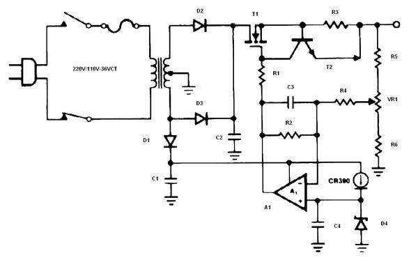
The schematic diagram originates from a circuit designed as a battery charger/power supply with an output of 14V and a maximum current of 4A, utilizing the VN64GA MOSFET. This high-performance battery charger is specifically engineered for gelled electrolyte lead-acid...
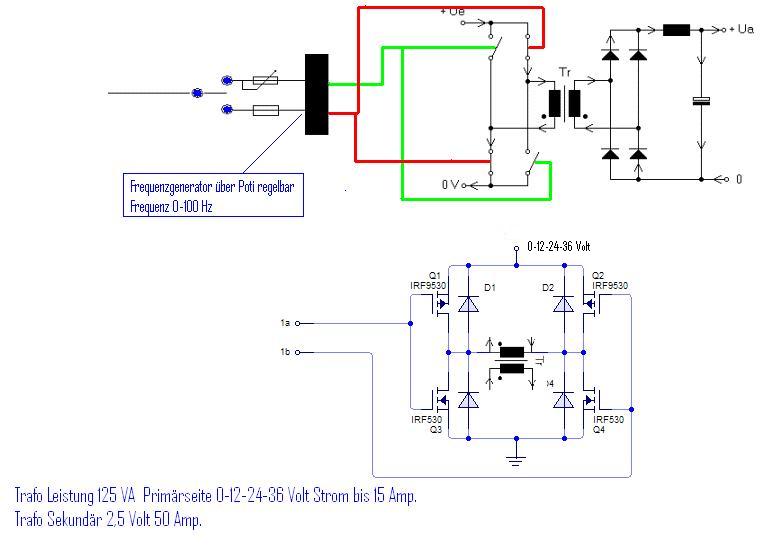
The simplest way to harness free available energy is by utilizing solar cells. A single efficient solar cell, when paired with a well-configured HHO generator, can produce a significant amount of gas suitable for various applications, all without incurring...
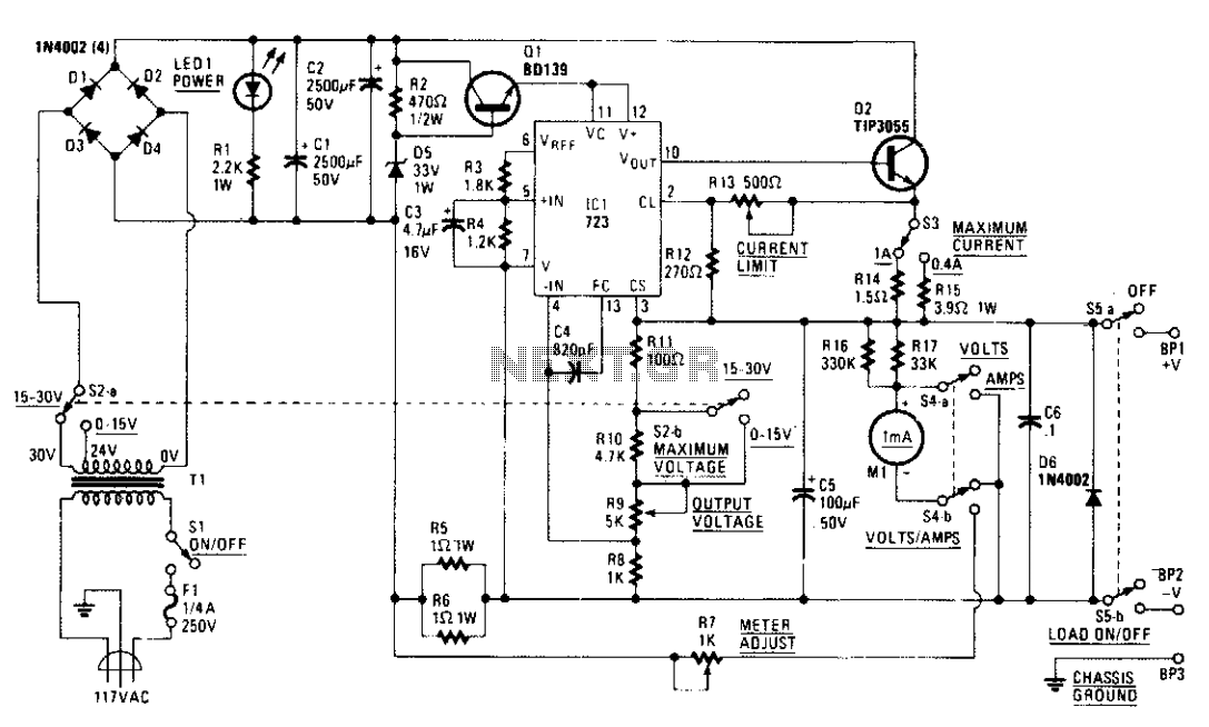
A tapped transformer drives a diode bridge (D1-D4) and two 2500 µF filter capacitors (C1 and C2), which provide a no-load voltage of 37 or 47 volts, depending on the position of switch S2a. The unregulated DC is then...
The circuit safely delivers approximately 20 Amps at 13.8V. For lower current applications, a separate current limiting output capable of 15mA up to a total of 20A has been included. The power transformer should be able to supply at...
The device shows a voltage of 24V at no load on pins +4, 5 and -7, 8. This configuration is referred to as a passive power injector. When a current draw of 1A was attempted from the device, it...
Warning: include(partials/cookie-banner.php): Failed to open stream: Permission denied in /var/www/html/nextgr/view-circuit.php on line 713
Warning: include(): Failed opening 'partials/cookie-banner.php' for inclusion (include_path='.:/usr/share/php') in /var/www/html/nextgr/view-circuit.php on line 713