
RF Signal Detector using TDA2822
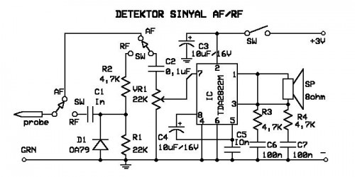
The signal detector circuit operates by utilizing a combination of components such as diodes, resistors, capacitors, and operational amplifiers to effectively identify the presence of signals. The circuit is capable of distinguishing between AF and RF signals, making it versatile for various applications including audio processing and radio communication.
The core of the circuit typically involves a diode that rectifies the incoming signal, converting it from AC to DC. This is crucial for the detection process, as the rectified voltage can be further analyzed or processed. Following the rectification, a low-pass filter may be employed to smooth the output signal, removing high-frequency noise that could interfere with the detection.
In order to enhance sensitivity and selectivity, operational amplifiers can be integrated into the design. These amplifiers are configured to amplify the rectified signal, allowing for better detection of weaker signals. The gain of the operational amplifiers can be adjusted through feedback resistors, providing flexibility in the circuit's performance.
Additionally, the circuit may include indicators such as LEDs or a meter to visually represent the detected signal strength. This feature is particularly useful in applications where monitoring signal presence is necessary.
The layout of the circuit is designed to be compact, making it suitable for portable applications. The simplicity of the design facilitates easy assembly, allowing both hobbyists and professionals to construct the signal detector with minimal effort.
Overall, this signal detector circuit is an effective tool for identifying AF and RF signals, with a design that emphasizes ease of construction and compactness, catering to a wide range of electronic projects.signal detector electronics that can be used to detect the signal does not AF / RF. This series is very neat and easy to make. 🔗 External reference
Related Circuits
The CA3189 integrated circuit (IC) incorporates a symmetrical limiter, a phase demodulator, an audio amplifier, and a logarithmic detector-amplifier. The logarithmic detector-amplifier is particularly noteworthy for enhancing the logarithmic signal meter of shortwave receivers, thereby improving signal reading accuracy....
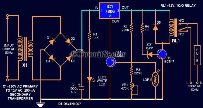
This circuit automates the control of street or porch lights. The automatic lamp controller circuit utilizes a 7806 voltage regulator IC, which can be employed to automate street lights, tube lights, or any other home electrical lighting systems. The...

This circuit is a simple metronome model designed for ease of use. It employs transistors as key components, specifically configured as an astable multivibrator, to produce a beeping sound. The tone can be adjusted using a variable resistor (VR1)....
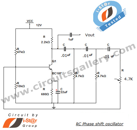
This section introduces a transistor oscillator circuit known as the RC Phase Shift Oscillator. An oscillator is an electronic circuit that functions as a sine wave generator, requiring only a DC power supply. It is commonly used in variable...
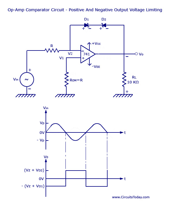
Voltage Limiter Circuit Using Op-amp - Circuit Diagram, Waveform, Positive and Negative Voltage Limiters. The voltage limiter circuit utilizing an operational amplifier (op-amp) serves to restrict the output voltage to predefined levels, effectively preventing it from exceeding or falling below...
Turning electrical devices ON or OFF using a remote control is a well-established concept, with numerous devices available that perform this function effectively. To create such a device, it is necessary to construct a receiver and a transmitter, as...