
Voltage Limiter Circuit Using Op-amp-Circuit Diagram Waveform

The voltage limiter circuit utilizing an operational amplifier (op-amp) serves to restrict the output voltage to predefined levels, effectively preventing it from exceeding or falling below specified thresholds. This circuit design can incorporate both positive and negative voltage limiters, which allows for comprehensive control over the output voltage range.
In the typical configuration of a voltage limiter circuit, the op-amp is employed in a feedback arrangement. The non-inverting input of the op-amp receives the input voltage signal, while the inverting input is connected to a reference voltage set by a voltage divider or Zener diode. The output of the op-amp is then fed back to the inverting input through a resistor, creating a closed-loop system.
To achieve positive voltage limiting, the reference voltage is set to the desired upper limit. When the input voltage exceeds this reference, the op-amp output will drive low, effectively clamping the output to the maximum allowable voltage. Conversely, for negative voltage limiting, a similar approach is adopted, where the reference voltage is set to the desired lower limit. This configuration ensures that the output voltage remains within the specified range, protecting downstream components from potential damage due to voltage spikes or dips.
The circuit can be visualized through a schematic diagram, which typically includes the op-amp, resistors for feedback and input scaling, and reference voltage sources. Additionally, waveforms can be illustrated to demonstrate the circuit's response to varying input voltages, showcasing how the output remains stable within the defined limits.
This voltage limiter circuit is widely applicable in various electronic systems, including power supplies, signal processing, and safety mechanisms, where voltage levels must be controlled to ensure reliable operation and protect sensitive components.Voltage Limiter Circuit Using Op-amp-Circuit Diagram, Waveform, positive and negative voltage limiters.. 🔗 External reference
Related Circuits
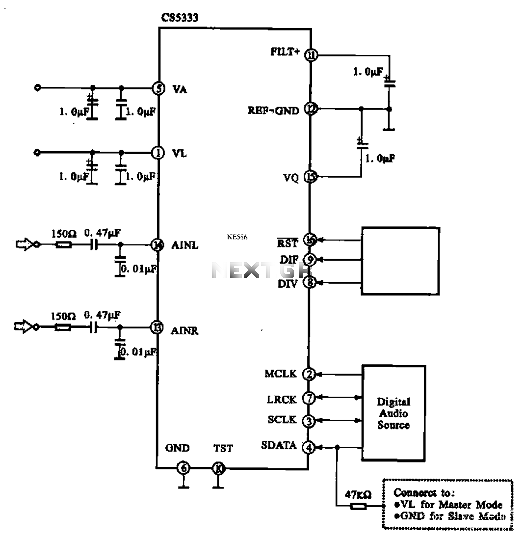
Audio A/D converter circuit configuration using the CS5333 chip, which is a high-performance 24-bit, 96 kHz stereo A/D converter commonly used in digital products. This circuit converts one or more audio signals into a digital signal for processing and...
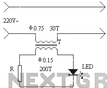
The installation of an electrical outlet in the refrigerator work light serves to enhance visibility of the refrigerator's interior while also improving the aesthetic appeal of the socket. The circuit is illustrated. Additionally, the circuit utilizes the secondary induced...
All Things Pros discusses various topics related to patent prosecution. It provides strategies for addressing rejections under sections 102, 103, 101, and 112, often in the context of Board of Patent Appeals and Interferences (BPAI) decisions. The content also...
A keyed power input connector, series rectifier and a shunt rectifier, both 1N4007, prevent reverse voltage from being applied to the power input. A 27 volt metal oxide varistor clamps the voltage to the 78L05 that follow it, to...
A frequency synthesizer circuit diagram has been found, but clarification is needed regarding a component connected to VDD from pin 9, VSS from pin 8, and pin 12, which is linked to the phase comparator 2. The component in...
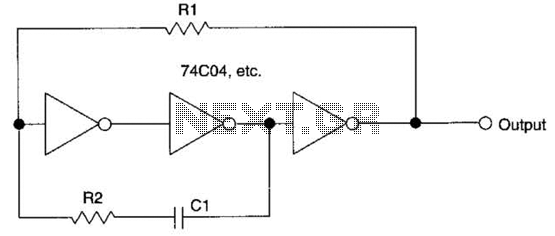
This circuit employs a protective resistor R2 along with a feedback resistor R1. Together, these components create a voltage divider that lowers the input voltage amplitude for IC1-a, ensuring that the protective diodes remain inactive. This arrangement enhances the...