
Simple Metronome using transistor

The design generates both light and sound signals, making it suitable for applications such as bicycle taillights or turn signals. The power supply circuit includes two transistors, Q1 and Q2, functioning as an astable multivibrator that continuously toggles between ON and OFF states. The collector pins (C) of both transistors are connected to a light source (LED1-LED4) and an audio source (buzzer BZ1). When one transistor is ON, the associated device connected to pin C operates, producing alternating light and sound signals.
The circuit generates a melody by employing a flasher circuit that activates a loudspeaker with a clicking sound. The PNP transistor (Q2, options include 2N3906, 2N2907, or BC558) operates based on the circuit's frequency, determined by the resistor-capacitor (RC) combination and the NPN transistor (Q1, options include 2N3904, 2N2222, or BC549). A 50K potentiometer (R2) is used to fine-tune the working rate, which can vary from 20 to 280 beats per minute (bpm). By changing the value of capacitor C1 (from 0.1 µF to 22 µF), the pitch of the sound produced can be altered. Higher-pitched tones can be achieved by using smaller capacitors, while adjusting a 10K resistor from fixed to variable can increase the voltage supplied to the circuit, although this may risk overheating or damaging the transistors.
The circuit has been tested with components including a 2N3904 transistor, a 2N3906 transistor, a 22 µF capacitor, a 10K resistor, a 50K trimmer resistor, and a piezo transducer. The necessity of a loudspeaker is contingent on the desired output sound quality and application.
The schematic for this metronome circuit should include the following components arranged as follows:
1. **Transistors**:
- Q1: NPN (e.g., 2N3904)
- Q2: PNP (e.g., 2N3906)
2. **Resistors**:
- R1: Fixed resistor (value as per design requirement)
- R2: 50K potentiometer for rate adjustment
- R3: 10K resistor (can be variable)
3. **Capacitors**:
- C1: Adjustable between 0.1 µF and 22 µF for tone variation
- C2: 10 µF for amplification adjustments
4. **Output Devices**:
- LEDs (LED1-LED4) for visual indication
- Buzzer (BZ1) for audio output
- Optional: Piezo transducer for sound generation
5. **Power Supply**:
- Ensure appropriate voltage supply to support transistor operation.
The circuit layout should clearly depict the connections between components, ensuring that the collector, base, and emitter of each transistor are correctly positioned for optimal functionality. The variable components should be labeled to facilitate adjustments during testing and operation.This circuit be Simple Metronome circuit model to be simple. It use the transistor be important equipment by very the circuit is the character Astable Multi vibrator. For produce something the sound beep. By can fine VR1 for get sound tone Generator follow can want. A loudspeaker that use to is supposed to impedance 8 32 ohm railing land. For decrease the popularity will down and may lead, output, go to feed reach still the amplifier microphone has changed, capacitors 10 uF. The detail is other, see in the circuit. This circuit is a simple signal. It can generate signals, both light and sound Alternating. Which can be applied to work. For example Taillight of bicycle or Turn left and the right of the bicycle. Etc. When entering into power supply circuit. by circuit will have Q1 and Q2 to be astable multi vibrator. This will work in any way ON and OFF. Or vice versa on all the time. And Pin Collection (C) of the two transistors. Connected to the light source device (LED1-LED4). For the audio source device is Buzzer BZ1. While the one ON transistor will allow the device is connected to pin C is running. The signal alternates between light and sound all the time. This is knock the melody. It uses begin flasher circuit in building sound click keen go up at a loudspeaker. But each time at PNP-transistor, Q2 type(2N3906-2N2907-or-BC558) work by origin frequency circuit that use RC and Q1-NPN transistor-type(2N3904 or 2N2222-or BC549), R2-potentiometer 50K is used for fine working rate repeatedly through 20-280 sections time per minute(tone), By value change of C1 (0.
1uF to 22uF) will change the tone of voice in the sound click at happens. You can get different (i. e. higher pitched) tones by messing with the capacitor value from 22uF to. 1uF electrolytics, and whatever other capacitors you may have in your parts box. By changing the 10K resistor from fixed to variable, you can increase the voltage going to the circuit, but at the risk of the transistors failing via overheating/overvoltage. I could not get mine to work. I was using a breadboard, 1 2N3904, 1 2N3906 and 22 uF capacitor and 1 10 k resistor and 50k trimmer resistor.
And a piezo transducer. Do I really need a speaker 🔗 External reference
Related Circuits
The Over-the-Top type of operational amplifier is ideal for use as a current sensor for battery charger applications. The design described here can be used with chargers for rechargeable batteries (Lead/acid or NiCd, etc.). The 5 V operating supply...
Figure 4-33 illustrates a circuit configuration that includes a common amplifier along with analog inductive circuits. In this setup, the transistor in the analog inductive circuit is utilized, and an increase in the bias resistor enhances circuit stability. A...
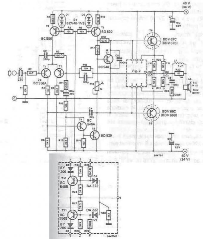
A high-power audio amplifier can be designed using power transistors and other common electronic components, capable of delivering a maximum output power of 90W. When using the specified component values, it can drive speakers with a 4-ohm impedance, resulting...
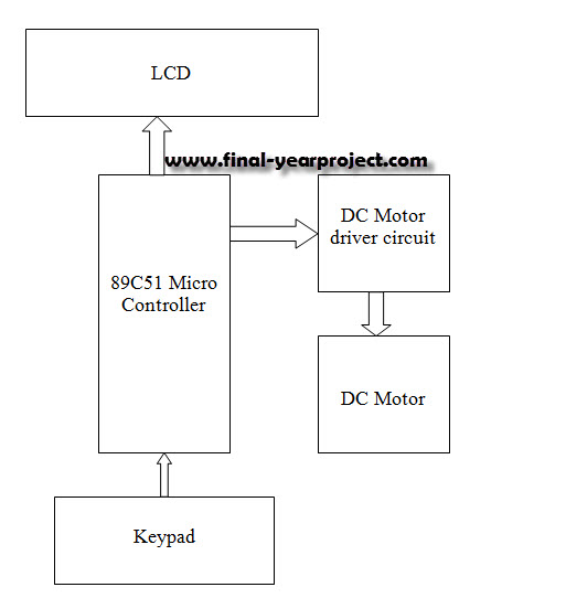
This report details an electronic project focused on the speed control of a DC motor using a microcontroller and PWM (Pulse Width Modulation). The system integrates a microcontroller with an LCD, keypad, and a DC motor driver. The microcontroller...
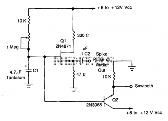
This simple oscillator utilizes a 2N4871 UJT to generate pulses ranging from 0.2 to approximately 20 Hz. A spike can be observed at C2, while a sawtooth waveform is present at the emitter of Q2, measuring about 2-3 V...
The light fader circuits described here share a common concept of creating a gradual "cool" switch ON and switch OFF effect for connected lamps. This means that each time the lights are activated, the result is a smooth transition...
Warning: include(partials/cookie-banner.php): Failed to open stream: Permission denied in /var/www/html/nextgr/view-circuit.php on line 713
Warning: include(): Failed opening 'partials/cookie-banner.php' for inclusion (include_path='.:/usr/share/php') in /var/www/html/nextgr/view-circuit.php on line 713