
5W Chinese PLL FM Transmitter With LCD Printed Circuit Board (PCB)
")
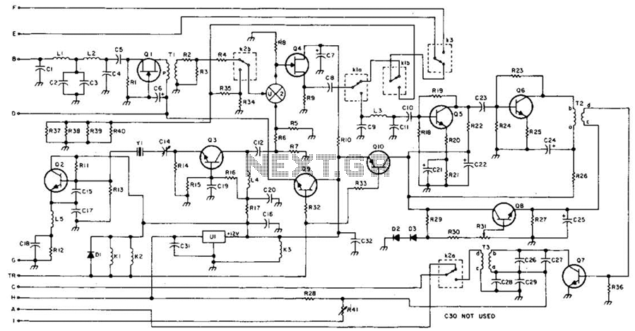
The PLL FM transmitter circuit described utilizes a phase-locked loop (PLL) architecture, which is essential for maintaining frequency stability in FM transmission. The core of this circuit is the SAA1057 PLL controller, which is responsible for frequency modulation and demodulation processes. The choice of the PIC16F628 microcontroller allows for additional programmability and customization of the transmitter's functions, enhancing its versatility in various applications.
The final power amplification stage employs the 2SC1971 transistor, known for its robust performance in RF applications. This transistor is capable of delivering sufficient output power to effectively drive the antenna, ensuring a clear signal over a considerable distance.
For flexibility in component selection, a list of alternative transistors is provided, allowing designers to substitute with equivalent parts such as BC547 for 2SC2458 or BD136 for 2SB562, among others. This adaptability can be particularly useful in regions where specific components may be difficult to source.
The printed circuit board (PCB) dimensions are specified as 155 mm by 120 mm, which provides a compact form factor suitable for various installation scenarios. The design incorporates coils made from 0.8 mm copper wire wound to a diameter of 6 mm, which is critical for achieving the desired inductance values necessary for the oscillator and filter stages of the transmitter.
Overall, this PLL FM transmitter circuit is designed to be user-friendly while offering a range of customization options through component substitution, making it a practical choice for both hobbyists and professionals in the field of electronics.Here's PLL FM transmitter circuit from china. This circuit uses the familiar 2SC1971 for final power amplifier stage. The PLL controller of the FM transmitter use SAA1057 and PIC16F628 (download HEX file). If want to change the active component, here's the list: 2SC2458 = BC547 2SA1048 = BC557 2SK192 = J310 2SB562 = BD136, BD138, BD140 2SC1923 = BF199 of BRF91 2SC1923 = BF199 or BRF91 2SC2053 = BRF96 2SB1135 = BD136, BD138, BD140 MV2105-09 = BB105, BB119 Printed Circuit Board (PCB) for this FM transmitter circuit is 155 mm x 120 mm. All coils are 0.8 mm copper wire with a 6 mm diameter. Please see parts used from schematic. 🔗 External reference
Related Circuits
This 49-MHz FM transmitter comprises an audio amplifier, a low-pass filter, three RF stages, and a regulated DC power supply. The output power is approximately 16 mW into a 50-ohm load. This transmitter is suitable for various 49-MHz applications,...

R4 prevents the output voltage from drifting toward one of the supply rails of the operational amplifier. It is understood that R4 should have a high resistance, although the reason for this is unclear. The schematic appears to be...
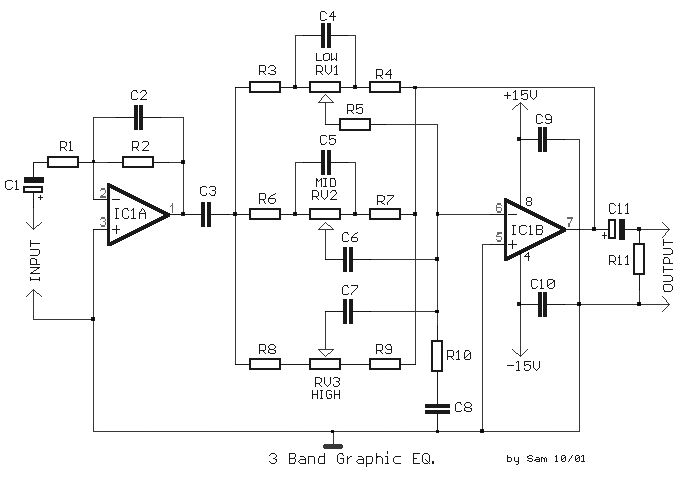
The circuit illustrates the use of three frequencies to produce a graphic equalizer that will be used for acoustic signals. The equalizer can be either passive or active. The graphic equalizer circuit operates by dividing the audio frequency spectrum into...
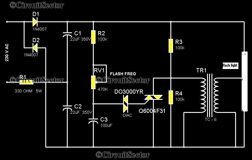
This circuit is a strobe light that allows for adjustable flashing rates. It utilizes a flash tube commonly found in cameras. In standard cameras, the flash may take ten to twenty seconds to recharge. However, this circuit enables the...
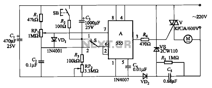
The circuit illustrated in Figure 3-12 incorporates variable speed and timing control functions. When switch S is set to position 1 and button SB is pressed, the motor initiates operation. After a predetermined delay, the motor automatically shuts down....
The simple bell circuit without IC. It includes a doorbell circuit that can produce different sounds using integrated circuits, transistors, and resistors. The circuit utilizes a coded trigger mechanism to differentiate between various visitors. When the button is pressed,...