
Wireless-fm-microphone

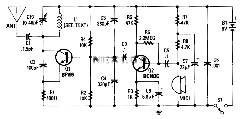
Transistor Q1 functions as an amplifier for the condenser microphone MIC1. The output from Q1 is fed to the base of transistor Q2 through a 4.7 µF capacitor. Capacitors C2 and L1 form an LC tank circuit, which is utilized to establish the operating frequency of the transmitter. Coil L1 is a variable inductor, slightly below 1 µH, that is employed to adjust the modulating frequency of the circuit. Capacitors C1 and C2 are both 4.7 pF units. A lower capacitance value can be utilized to increase the operating frequency of the circuit. The microphone and Q1 generate a varying voltage at the base of Q2, with the output of Q2 directed to the LC tank circuit. This interaction induces a modulating action in the tank circuit that, when transmitted through an antenna—a short wire measuring 6 to 8 inches—produces a clear FM signal within the frequency range of 88 to 95 MHz, achieving a transmission range of approximately 100 feet.
The circuit described utilizes two transistors, Q1 and Q2, to amplify the audio signal captured by the condenser microphone MIC1. The first stage, involving Q1, amplifies the weak audio signal from the microphone, which is then coupled to the base of the second transistor, Q2, through a coupling capacitor (C1). The value of this capacitor is critical as it allows the AC audio signal to pass while blocking any DC component, ensuring that only the modulated signal influences the operation of Q2.
The LC tank circuit, formed by capacitors C2 and inductor L1, plays a vital role in determining the frequency of oscillation for the transmitter. The variable inductor L1 allows for fine-tuning of the frequency, enabling adjustments to be made based on desired transmission characteristics. The capacitors, particularly C2, can also be varied; using a lower capacitance value will effectively increase the frequency of operation, which can be advantageous depending on the specific application or regulatory requirements.
The output from Q2 is applied to the LC tank circuit, where the modulating action occurs. This circuit resonates at the selected frequency, allowing for efficient energy transfer to the antenna. The antenna, constructed from a short wire segment, radiates the modulated signal into the environment. The specified frequency range of 88 to 95 MHz is typical for FM broadcasting, and the effective range of approximately 100 feet indicates that this circuit is suitable for short-range communication applications.
Overall, this circuit demonstrates a straightforward but effective method for creating an FM transmitter capable of amplifying audio signals from a microphone and transmitting them over a limited distance. The design allows for frequency adjustments and provides a clear output signal, making it suitable for various applications in wireless audio transmission.Transistor Q1 acts as an amplifier for condenser microphone MIC1. The output of Q1 is applied to the base of transistor Q2 through a 4. 7 -I"F capacitor. C2 and 11 form an LC tank circuit. which is used to set the frequency at which the transmitter operates. Coil 11 is a variable inductor, centered a bit below 1~tH, that is used to adjust the modulating frequency of the circuit. Capacitors C1 and C2 are 4. 7 pF units. A lower value can be used to raise the circuit"s operating frequency. The microphone and Q1 provide a varying voltage at the base of Q2, with the output of Q2 applied to the LCtank circuit.
That causes a modulating action in the tank circuit that, when applied to the antenna, a short piece of wire 6-to 8-inches long, will provide a good, clear FM signal somewhere in the range of 88 to 95 MHz with a range of about 100 feet.
Related Circuits

Utilize standard RF wiring precautions. Optimal speech clarity is achieved by employing an electret microphone. For music reproduction, replace it with a dynamic microphone element. In the design of audio circuits, particularly those involving speech and music, the choice of...
An adjustable capacitor C10 and a coil L1 create a tank circuit that, along with Q1, C2, and R1, oscillates at a frequency within the FM band. The center frequency is adjustable by tuning C10. An electret microphone, M1,...