
RGB To Color Difference Converter
The circuit utilizes two LT1398 operational amplifiers, which are precision devices known for their low noise and high-speed performance, making them suitable for applications requiring accurate signal processing. The architecture is designed to handle RGB signals, with each color channel processed through dedicated paths that ensure minimal signal degradation and optimal impedance matching.
The operational amplifiers are configured to perform both summation and amplification tasks. IC1a is tasked with creating the R-Y color difference signal, while IC2a amplifies the Y signal for further processing. Similarly, IC1b combines the contributions from the G and B channels to produce the B-Y signal, ensuring that the output signals are appropriately scaled for downstream applications.
The use of 75-ohm coaxial cables indicates that the circuit is intended for high-frequency applications, such as video signal processing, where maintaining signal integrity is crucial. The termination resistors R11, R8, R10, and R12 are strategically placed to match the characteristic impedance of the coaxial cables, minimizing reflections and signal loss.
In summary, this circuit diagram represents a sophisticated approach to generating color-difference signals from RGB inputs, employing careful design considerations to ensure high fidelity and accurate signal processing in electronic applications. The overall design is efficient, drawing a modest current from a stable power supply while maintaining the integrity of the input signals throughout the amplification and processing stages.The circuit diagram shows two LT1398`s from Linear Technology used to create buffered color-difference signals from RGB (red-green-blue) inputs. In this application, the R input arrives via 75 coax. It is routed to the non-inverting input of amplifier IC1a and to 1. 07-k resistor, R8. There is also an 80. 6- termination resistor R11, which yields a 75- input impedance at the R input when considered in parallel with R8. R8 connects to the inverting input of a second LT1398 amplifier (IC1b), which also sums the weighted G and B inputs to create a 0. 5Y output. Yet another LT1398 amplifier, IC2a, then takes the 0. 5Y output and amplifies it by a gain of 2, resulting in the +Y output. Amplifier IC1a is configured for a non-inverting gain of 2 with the bottom of the gain resistor R2 tied to the Y output.
The output IC1a thus results in the color-difference output R Y. The B input is similar to the R input. Here, R13 when considered in parallel with R10 yields a 75- input impedance. R10 also connects to the inverting input of amplier IC1b, adding the B contribution to the Y signal as discussed above. Amplifier IC2b is congured to supply a non-inverting gain of 2 with the bottom of the gain resistor R4 tied to the Y output.
The output of IC2b thus results in the color-difference output B Y. The G input also arrives via 75- coax and adds its contribution to the Y signal via resistor R9, which is tied to the inverting input of amplifier IC1b. Here, R12 and R9 provide the 75 termination impedance. Using superposition, it is straightforward to determine the output of IC1b. Although inverted, it sums the R, G and B signals to the standard proportions of 0. 3R, 0. 59G and 0. 11B that are used to create the Y signal. Amplifier IC2a then inverts and amplifies the signal by 2, resulting in the Y output. The converter draws a current of about 30mA from a symmetrical 5-volt supply. 🔗 External reference
Related Circuits
This document presents a straightforward and practical schematic for a 12V to 3V converter circuit. The output current of the circuit is approximately 1A. The 12V to 3V converter circuit is typically designed using a linear voltage regulator or a...
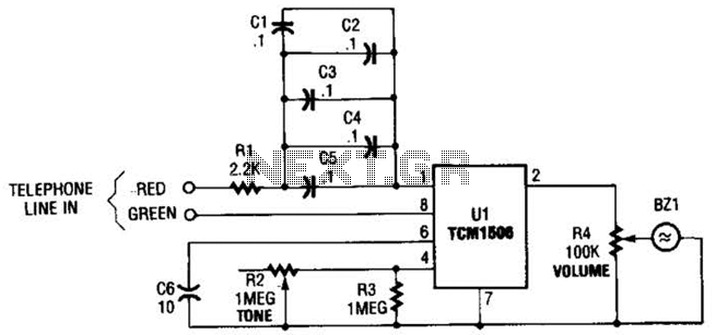
The circuit utilizes the TCM1506 ring detector/driver integrated circuit, which is a monolithic IC designed to replace mechanical bells in telephones. It is powered and activated by the telephone line's ringing signal, which ranges from 40 to 150 V...
Chapter 4, part five of a five-part series titled "Some Thoughts on DC/DC Converters," authored by the late Jim Williams and Brian Huffman, is included in Volume II of the book "Analog Circuit Design-- Immersion in the Black Art...
A frequency meter can be utilized in speed sensors, tachometers, or any application that requires the measurement of repetitive signals. This frequency-to-voltage converter (FVC) is designed to facilitate the conversion process. The frequency meter is an essential instrument in various...
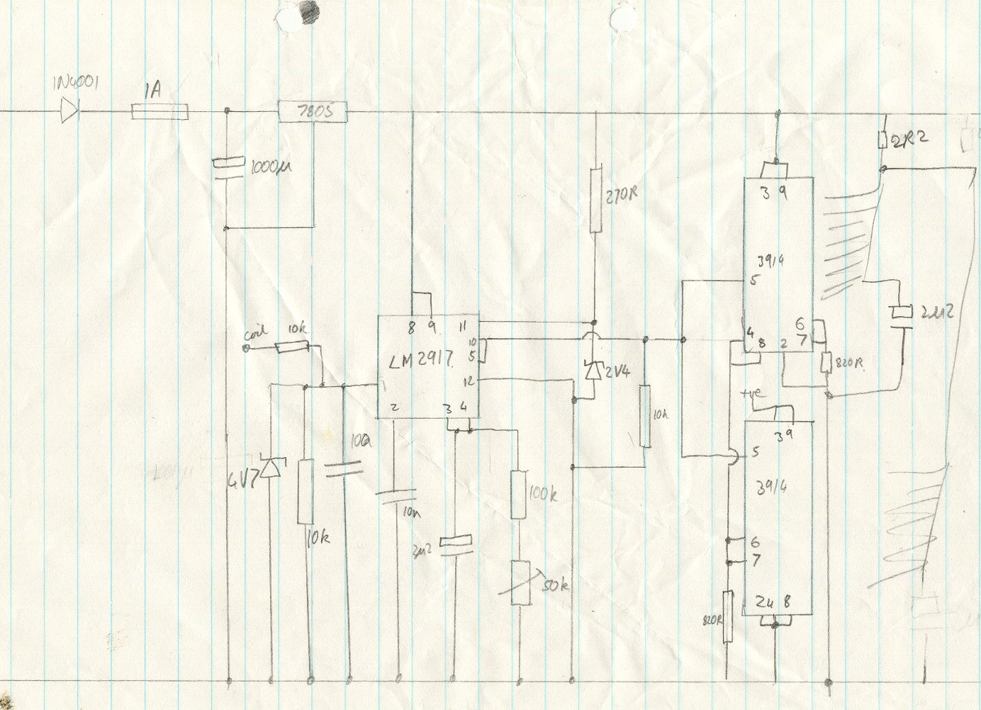
This circuit utilizes an LM2917 frequency-to-voltage converter. The input is connected to the low voltage side of the ignition coil, with various components designed to produce a full-scale output at 6000 RPM, corresponding to 12000 ignition pulses per minute,...
This inverter circuit can provide up to 800mA of 12V power from a 6V supply. For example, you could run 12V car accessories in a 6V car. The circuit is simple, about 75% efficient and quite useful. By changing...