
Telephone Ring Converter Circuit
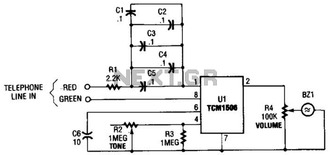
Resistor R1 is connected in series with the capacitor network to dissipate power from any high-voltage transients that may appear across the line. The attenuated AC voltage reaching pin 1 of U1 powers the chip. Capacitor C6 is included to prevent bell tapping, which is the unwanted ringing of the bell when a phone on the same line is used to dial an outgoing call. This capacitor blocks short dial pulses from activating the ring detector while allowing the longer ring signal to trigger it. Potentiometer R2 adjusts the tone of the ring signal, varying it from below 100 Hz to over 15 kHz. Potentiometer R4 serves as the volume control; setting this potentiometer to its lowest resistance mutes the piezo element (BZ1). When a ringing signal is detected on the phone line, it powers U1, which generates a tone with a frequency determined by R2 and an amplitude set by R4, producing sound through BZ1.
The TCM1506 ring detector/driver circuit is designed to efficiently manage ringing signals in telephone systems. It operates by detecting the AC ringing voltage, which is critical for activating the internal circuitry of the IC. The capacitor network serves a dual purpose: it allows the AC signal to pass while blocking any DC offset, ensuring that only the ringing signal is processed. The careful selection of capacitor values and ratings is crucial to prevent damage from high-voltage transients, which can occur during line disturbances.
The inclusion of C6 is significant in preventing false triggering of the detector during dialing, a common issue in shared line applications. This capacitor's role is to filter out the short pulses generated when dialing, allowing only the sustained ringing signal to activate the detection circuitry. The use of potentiometers for tone and volume control provides flexibility in the circuit's operation, allowing end-users to customize their ringing experience.
The piezo element (BZ1) is the final output device, converting the electrical signals generated by the TCM1506 into audible sound. The interaction between the various components ensures that the circuit not only performs reliably but also meets the user’s preferences for sound characteristics. This design exemplifies the integration of modern electronic components in traditional applications, enhancing functionality while maintaining simplicity. The circuit is based on the TCM1506 ring detector/driver integrated circuit. It is a monolithic IC specifically designed to replace-the telephone`s mechanical bell. The chip is powered and activated by the telephone-line ring, which can vary from 40 to 150 V rms at a frequency of from 15 to 68 Hz. No other source of power is required. Again, referring to the figure shown, CI through C5 are placed in parallel to form a 0.5- capacitor that conducts the ac ring voltage to pin 1 of the TCM1506, but blocks any dc component.
Of course, those capacitors can be replaced by a single 0.47- to 0.5- capacitor provided that it has at least a 400-WVdc rating. Resistor Rl is in series with the capacitor network and is used to dissipate power from any high-voltage transient that might appear across the line. The diluted ac voltage that reaches pin 1 on Ul powers the chip. Capacitor C6 is used to prevent bell tapping. That is an annoying ringing of the bell that occurs when a phone on the same line is used to dial an outgoing call.
The capacitor prevents the short dial pulses from triggering the ring detector, but still allows the much longer ring signal to activate it. Potentiometer R2 is used to vary the tone of the ring signal from below 100 Hz to over 15 kHz. Potentiometer R4 is the volume control; adjusting that potentiometer to its lowest resistance will mute the piezo element (BZ1).
When a ring signal is present on the phone-line, it powers Ul. The IC then generates a tone (with a frequency that is determined by R2 and an amplitude set by R4) that is reproduced by BZ1. 🔗 External reference
Related Circuits
This circuit is a motion detection sensor that utilizes a light source and detector as an infrared motion detector. The motion sensor employs an infrared LED and a phototransistor. Since it relies on light, the sensor's sensitivity can be...
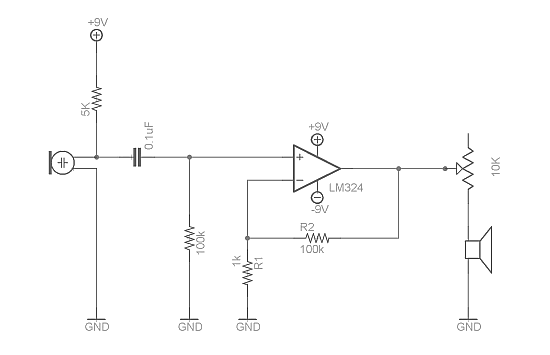
Afroman discusses the fundamentals of utilizing an operational amplifier to amplify small voltage signals and constructs a circuit designed to detect very faint sounds using a microphone. For further details about amplifiers, it is recommended to search for inverting...
This circuit combines two or more audio channels into a single channel (for example, converting stereo to mono). It is designed to handle any number of channels while consuming minimal power. The schematic illustrates two input channels, but additional...
The design of the digital logic probe centers around a pair of complementary bipolar transistors, which, in this application, are used as electronic switches. The digital logic probe is a diagnostic tool utilized for testing and analyzing digital circuits. The...
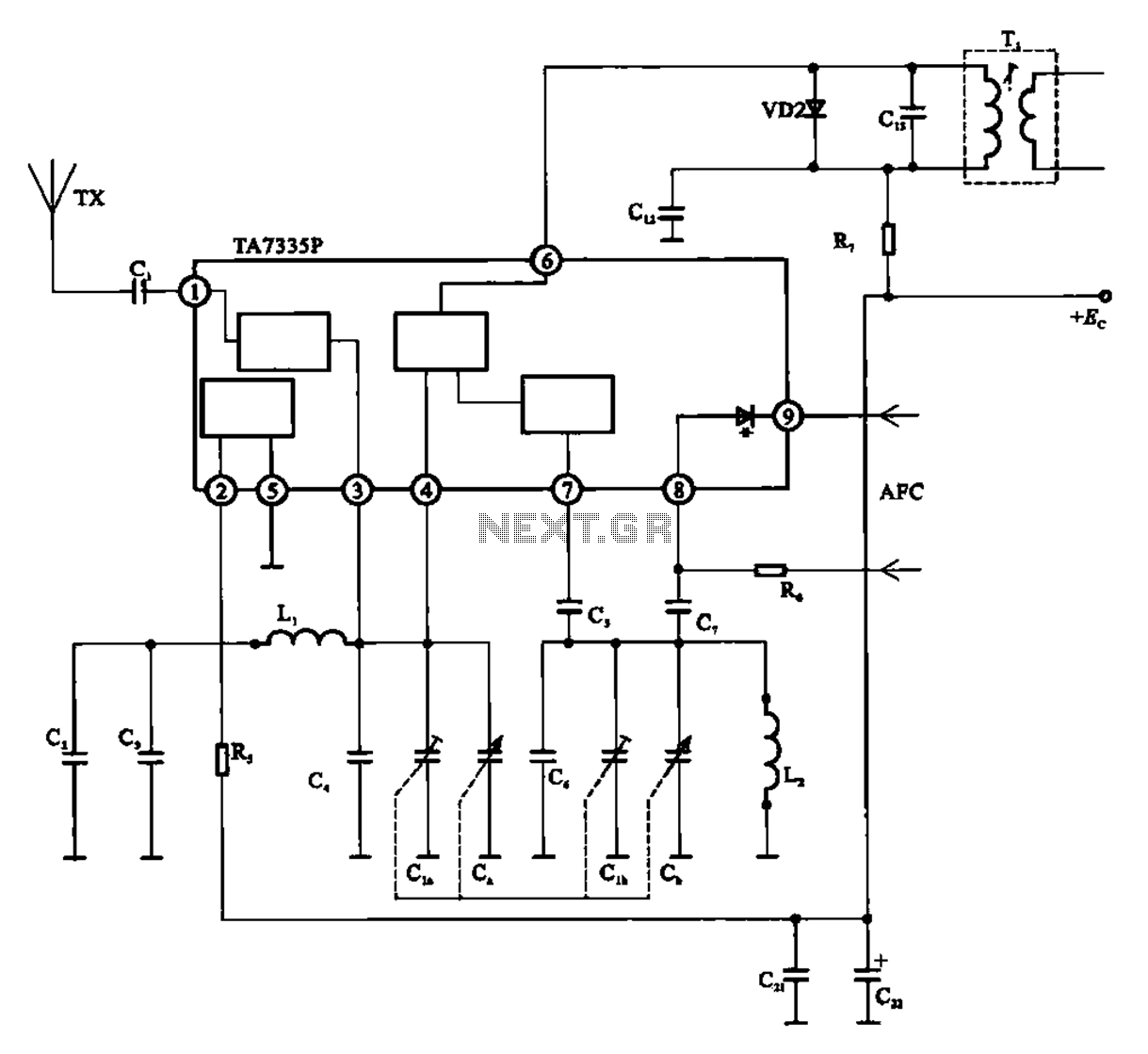
The FM front-end circuit, also referred to as an FM receiver circuit, is composed of discrete components. This configuration presents challenges in debugging and is prone to difficulties in miniaturization, leading to its gradual replacement by FM radio integrated...
The core of the circuit is a two-transistor flasher with frequency modulation applied to the base of the first transistor. When the pushbutton is pressed, the oscillation frequency increases to a peak, and upon release, the frequency decreases due...