
Simple and practical circuit diagram of an elevator failure alarm
The sound alarm circuit is a critical safety feature in elevator systems, designed to provide immediate notification of power outages that could leave passengers stranded. The circuit employs a combination of timers, transistors, and relays to ensure that the alarm is activated promptly and operates effectively. The use of a 6V battery ensures that the system remains functional even during a power outage, while the charging circuit guarantees that the battery is replenished when power is restored. The integration of the NE555 timer ICs allows for precise control over the alarm duration and frequency, ensuring that the alarm is both audible and effective in alerting the duty officer. The design emphasizes reliability and safety, making it an essential component of modern elevator systems. As we all know, if the elevator power suddenly fails, the distance distribution room duty officer is not immediately found, this time, the crew was on the elevator might panic. Here are a sound alarm circuit, as shown below, as long as the elevator of a power failure, the elevator distribution room will issue a sound alarm signal. The circuit works as follows: a circuit powered by a 6V battery, AC power once the elevator failure, the circuit that is audible alarm, the alarm time can be set in advance.
Alarm to a certain time, the end of the alarm sound, the duty officer to find fault immediately. Once troubleshooting, power restoration work, reported glanced circuit is cut off, while the battery will power the AC voltage charging. On 230V AC power by the step-down transformer X1 battery charging diodes D1, D2 rectified after Manifold IC4 (LM7806) regulator, the battery via a diode D5 and RLI relay normally closed contact (N/C) for charging.
When the battery is charging, transistor T1 through the diode D4 is turned, causing the tube T2 is turned off, no current flows through the relay RL1 because without work, the result has been in a state of charge of the battery. The maximum value of the charging voltage of 6V plus D5 pressure drop. Once an AC power failure (eg open circuit), the transistor T1 off, T2 is turned on, the relay pull a job, the normally closed (N/C) contact opens make contact (N/0) is turned on, the rechargeable battery loop is cut off.
At the same time, the timer IC2 and IC3 through the relay RLI closed contact (N/0) with battery-on operation. Timer IC3 (NE555) (3) feet of the output pulse signal 1KH2 deactivated IC2 (NE555) reset terminal (4) feet, IC2 works in pulsed mode, (3) an output signal pin of IC2 via the audio amplifier IC5 amplification, push speaker sound an alarm, indicating that the AC broke down.
Related Circuits
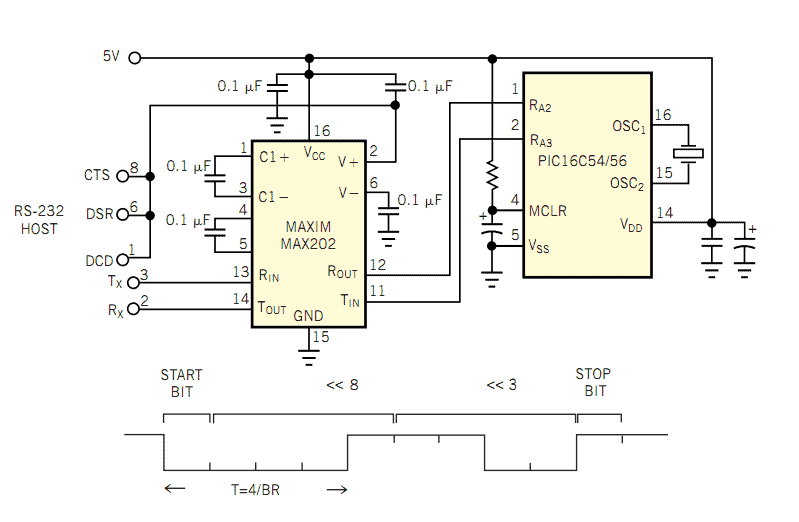
The popularity and easy access of RS-232 ports lend them to many communication projects. You can use a port as is or as a tiny parallel port when the exchange uses only control lines. Before the asynchronous serial-data transfer...
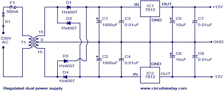
The circuit described is a regulated dual power supply that provides +12V and -12V from the AC mains. Such a power supply is an essential tool for electronic hobbyists. The transformer T1 reduces the AC mains voltage, while diodes...
For a robot to perform its assigned tasks, a controller is necessary. This controller may be mechanical, electrical, electronic, or a combination of these. It acts as the brain of the entire system, providing the robot with its intelligence....
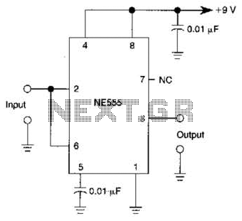
A 555 IC is configured to function as a Schmitt trigger. Inputs above and below the threshold level will turn the circuit on and off, producing a square wave output. The 555 timer integrated circuit (IC) is a versatile device...
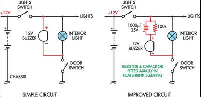
Two headlight reminder circuits are designed for easy installation and operation based on the KISS (Keep It Simple Stupid) principle. The basic circuit consists of a 12V piezo buzzer connected between the lights circuit and a door switch. The...
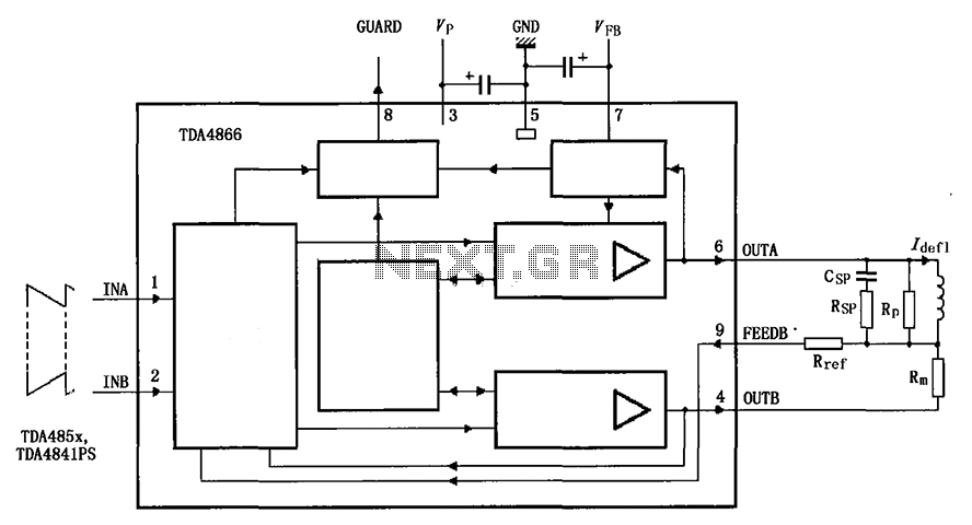
The TDA4866 is a 90-color power amplifier designed for vertical deflection systems, operating at a frequency range of 50 to 160 Hz. The CRMM circuit is implemented to ensure a high current drive input. The amplifier features a dual...