
RING COUNTER WITH VISUAL READOUT
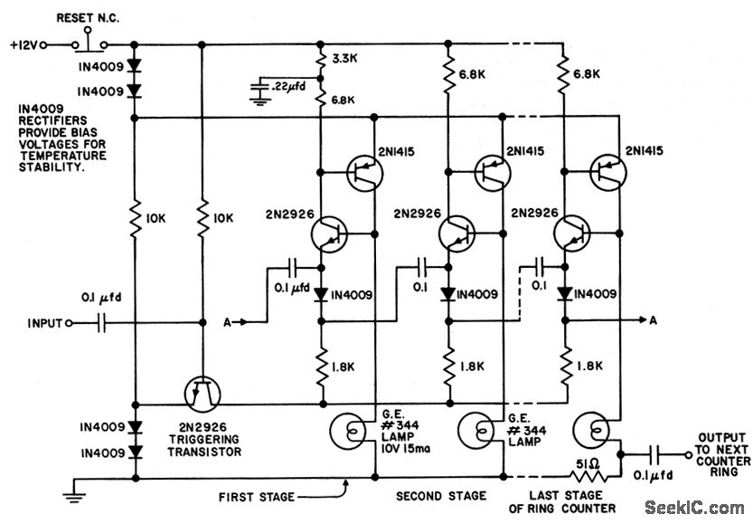
The described circuit is designed to operate efficiently with a minimal number of components, specifically six per stage. This streamlined approach not only simplifies the assembly but also contributes to reduced power consumption, making it suitable for battery-operated applications. The combination of counter and indicator functionalities within each stage allows for versatile operation, where the circuit can indicate various states while consuming little energy.
The activation of the first stage is facilitated by a 0.22 µF capacitor, which plays a crucial role in ensuring that the circuit powers up correctly after the reset button is released. This capacitor charges and provides the necessary voltage to initiate the operation of the first stage, ensuring reliable performance.
Current flow is optimized such that it only occurs when the lamp is turned on, which further conserves battery life. This characteristic is particularly beneficial in applications where prolonged operation is required without frequent battery replacements.
The modular design of the circuit allows for scalability, enabling the addition of multiple stages in a ring configuration. This flexibility makes it applicable for various uses, such as in decorative lighting systems or indicators where multiple states need to be displayed in sequence. Each stage can function independently, yet they collectively contribute to the overall operation of the circuit.
In summary, the circuit's efficient design, low power consumption, and modular capabilities make it a practical solution for applications requiring minimal component use while maintaining functionality and performance.Uses only six components per stage. Combining of counter and indicator functions gives low battery drain. After reset button is re leased, 0. 22-mid capacitor insures that first stage turns on. Current is drown by stage only when lamp is on. Any number of stages may be included in ring. -"Transistor Manual, " Seventh Edition, General Electric Co. , 19 64, p 203. 🔗 External reference
Related Circuits
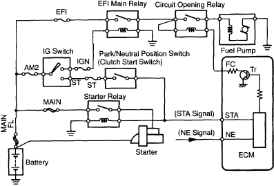
1997 Toyota Camry Fuel Pump Wiring Diagram. The fuel pump wiring diagram for the 1997 Toyota Camry provides a detailed representation of the electrical connections associated with the vehicle's fuel pump system. This diagram typically includes the power supply lines,...
This product includes logic circuitry utilized to control the timing of the output pulses, which will be discussed in a later step. The product features a logic circuit that is integral to managing the timing of output pulses. This...
The schematic for the Bee Counter test board includes labeled functional units for ease of discussion. This test board features the same circuitry as the larger version but is simplified to include only four gates instead of forty-four, significantly...
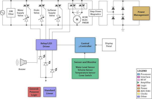
Many of today's appliances feature displays and buttons. Instead of relying on motors and gears, numerous household items now incorporate embedded microcontrollers. This exploration focuses on how to experiment with microcontrollers at home. Microcontrollers serve as the central processing units...
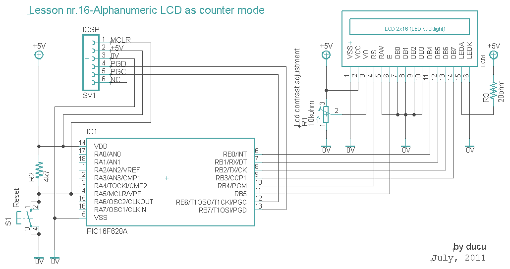
The communication technique with the LCD is similar to the previous lesson. In this experiment, a counter that counts from 0000 to 9999 has been added. The counter increments with a 1-second delay. The communication with the LCD will...
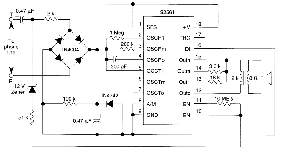
This telephone ringer utilizes an AMI chip with part number S2561 and can be powered directly from the telephone line. The audio output is approximately 50 mW when supplied with a 10-V source. The circuit design of the telephone ringer...