
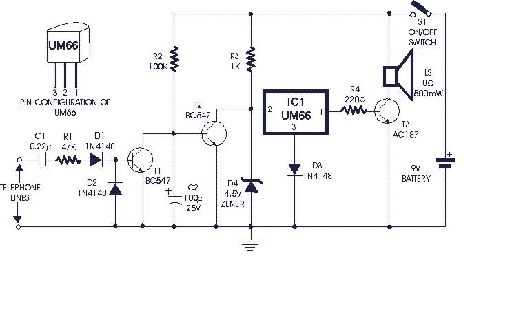
TELEPHONE RINGER
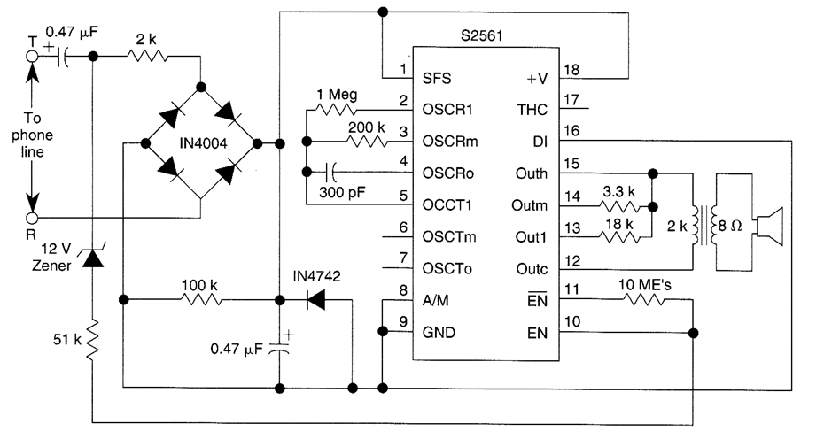
The circuit design of the telephone ringer based on the AMI S2561 chip incorporates several key components to ensure efficient operation and reliable performance. The S2561 chip is specifically designed for telephone applications, providing a compact solution for ringing signals.
The power supply for the ringer is derived from the telephone line, which typically operates at a voltage range of 48 V during idle conditions and can drop to around 10 V during ringing. The circuit must include a voltage regulator or a suitable rectifier to ensure that the S2561 chip receives a stable 10-V supply, which is essential for maintaining consistent audio output.
The audio output stage of the circuit is designed to deliver around 50 mW of power, sufficient for driving a typical telephone ringer speaker. This is achieved through a combination of amplification circuits that may include transistors or operational amplifiers configured to boost the signal from the S2561 chip to the desired power level.
Furthermore, the circuit may incorporate filtering components, such as capacitors and inductors, to eliminate any unwanted noise and ensure that the ringing tone is clear and audible. The output stage should also be protected with appropriate components to prevent damage from voltage spikes that may occur on the telephone line.
In summary, the telephone ringer circuit utilizing the AMI S2561 chip is a robust solution for generating ringing signals, powered directly from the telephone line, with an output capable of delivering 50 mW of audio power when operated at a 10-V supply. Proper attention to power regulation, amplification, and signal conditioning is essential for optimal performance.Using an AMI chip P/N S2561, this telephone ringer can be powered line. Audio output is about 50 mW when powered from a 10-V source.. 🔗 External reference
Related Circuits
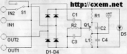
FM Telephone Bug. This is a simple transmitter that, when connected to a phone line, will transmit any audio on that line (except the dial tone) to any FM radio. The FM Telephone Bug is designed to intercept and transmit...
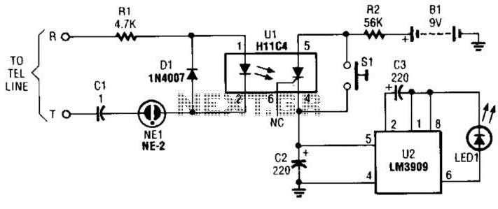
The circuit is constructed using a pair of low-cost integrated circuits (ICs): an H11C4 optoisolator/coupler with a silicon-controlled rectifier (SCR) output (U1) and an LM3909 LED flasher (U2). It connects to the phone line in the same way as...
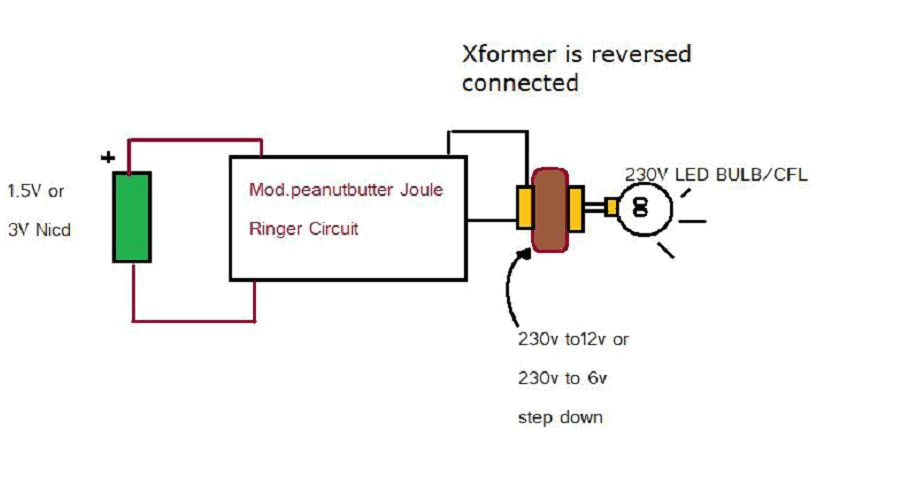
Various threads on ringer circuits have been observed, showcasing multiple variants, particularly concerning the types of transformers utilized, such as air core and step-down transformers. One notable circuit is the 12V-to-120V configuration, which employs a joule ringer that utilizes...
The standard telephone bell can be quite bothersome, especially at night when disturbance is undesirable. The circuit presented here transforms the loud ringing bell into a gentle and pleasant musical tone. This circuit utilizes a tone generator to replace the...
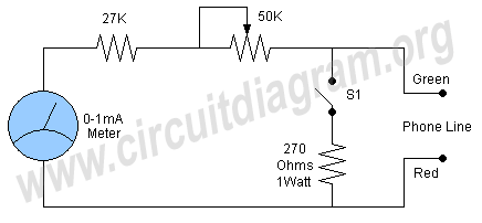
A simple and easy telephone line tester circuit that can be used for testing telephone lines. The telephone line tester circuit is designed to verify the functionality and integrity of telephone lines. It typically comprises a few essential components, including...
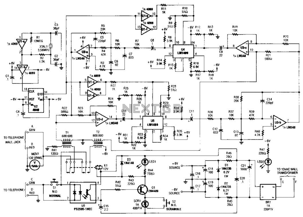
Two hybrids (T1 and T2) are utilized to facilitate a direct connection to a telephone line. This circuit employs a standard speech-inversion algorithm, which inverts the frequency of an audio signal around a central frequency. An LM1496 balanced modulator...
Warning: include(partials/cookie-banner.php): Failed to open stream: Permission denied in /var/www/html/nextgr/view-circuit.php on line 713
Warning: include(): Failed opening 'partials/cookie-banner.php' for inclusion (include_path='.:/usr/share/php') in /var/www/html/nextgr/view-circuit.php on line 713