
Bee Counter Theory
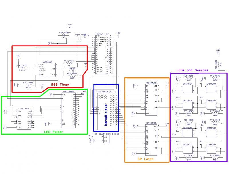
To summarize, the 555 timer circuit (highlighted in red) generates short pulses to activate the sensor LEDs. These pulses are directed to the LED pulser circuit (shown in green), where they are distributed to two sets of four LEDs. This configuration allows for the simultaneous pulsing of four LEDs at a time (indicated in purple), which also results in pulsing any signals from the sensors. The SR latches (depicted in orange) capture recorded signals by latching any high voltage, enabling the microcontroller to read the sensor states without needing to synchronize with the LED pulsing. After the microcontroller reads the state of each latch, it resets them to prepare for the next measurement. The demultiplexer facilitates communication between the microcontroller and over 88 sensor pins, allowing for reading and resetting of each sensor with a minimal number of microcontroller pins—potentially as few as fifteen pins for forty-four sensors.
The Bee Counter test board schematic is designed with efficiency and simplicity in mind, enabling effective testing and debugging of the overall system. The 555 timer circuit serves as the timing mechanism, providing consistent pulse outputs that are critical for the operation of the sensor LEDs. The LED pulser circuit is responsible for controlling the timing and sequencing of the LED activation, ensuring that the sensors are adequately illuminated during their operational cycles.
The SR latch configuration is integral to the design, as it allows the microcontroller to capture and store sensor readings independently of the LED pulsing. This asynchronous operation is crucial for accurate data collection, as it prevents the interference of LED activation with sensor signal readings. The microcontroller's ability to reset the latches after reading ensures that the system is ready for new data, thereby maintaining a continuous flow of information.
The implementation of a demultiplexer within the circuit architecture is a strategic choice that optimizes the use of microcontroller pins. By allowing multiple sensor inputs to be managed with fewer pins, the design enhances scalability and flexibility, making it easier to expand the system in future iterations or adaptations. This careful consideration of component selection and circuit layout reflects a well-thought-out approach to designing a functional and effective Bee Counter system.Here's the schematic for my Bee Counter test board with the functional units labeled to make them easier to discuss. This test board has the same circuitry as the larger board, but with only 4 gates instead of 44 to save a TON of time and money debugging it.
I should warn you that I haven't seen it work yet, so there's nearly a 100% chance that it won't work as drawn, but I'm pretty confident the design is solid even if my wiring or resistor values are off a bit, or if I somehow specified chips that won't work together. To summarize, the 555 timer circuit (in red) puts out short pulses that will be used to pulse the sensor LEDs. The pulses are sent to the LED pulser circuit (green). There they are routed to each set of 4 LEDs (only 2 sets in this test board). This pulses the LEDs 4 at a time (purple), but this means that any signal from the sensors is pulsed as well.
The SR Latches (orange) save a recorded signal (latching any high voltage) so the microcontroller can read the sensors without synchronizing the reading with the LED pulsing. After reading the state of each latch, the microcontroller will reset each latch so they're ready to record another measurement.
The demultiplexer simply allows the microcontroller to read and write to the 88+ sensor pins (read and reset for each sensor) with a minimum number of microcontroller pins (as few as 15 pins for 44 sensors) 🔗 External reference
Related Circuits
This is a schematic and block diagram of a 2-MHz frequency counter. It employs an LSI counter/display driver, an LCD readout, and several logic chips for timebase and timing pulse circuitry. Transistors Q2 and Q3 form a signal input...
The circuit comprises a Microchip PIC 16F84 microcontroller and an LCD text module. The author claims that this counter can measure frequencies ranging from 400 Hz to 50 MHz. A faster version, the 20 MHz PIC 16F84A-20I/P, was utilized,...
Programming of the PIC microcontroller is required prior to its utilization in this circuit, which necessitates the use of a programmer. A suitable programmer can be located by searching for "Multi-PIC Programmer." The PIC microcontroller serves as the core component...

The circuit for the Digital Tachometer/RPM Counter consists of a few components. They should be connected according to the provided circuit diagram. The PIC used is on a demonstration board, meaning the clock, power, and ground pins are already...

SM indicates that the tube can produce certain frequencies and discusses the use of TV tubes to achieve improved sound quality at higher frequencies. The effectiveness of this approach can only be determined through experimentation with the specified frequency...
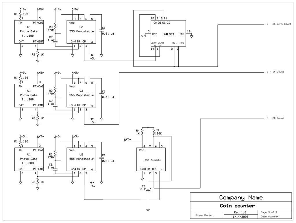
The next counter section operates similarly but is designed to count four quarters, single $1 coins (loonies), and single $2 coins (toonies). The circuit for the toonies is configured. The circuit for the counter section includes a digital counting mechanism...