
Ring Modulator
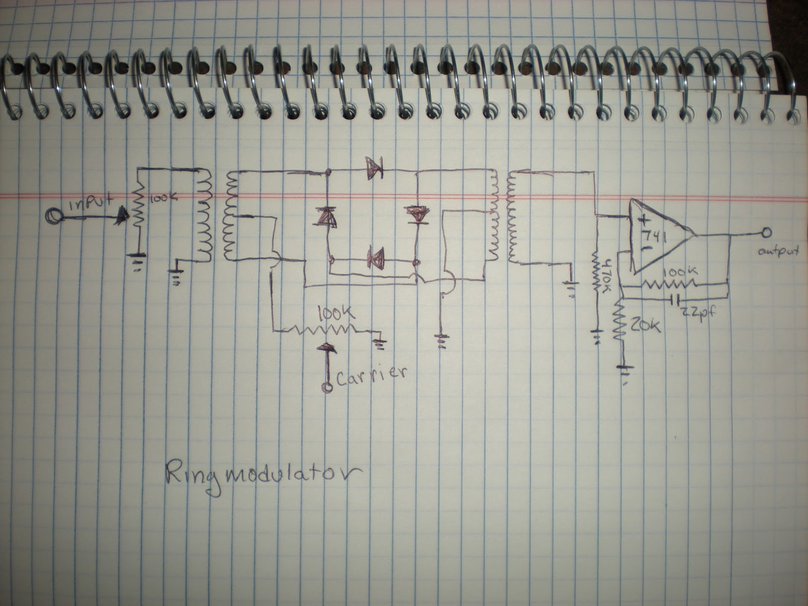
The updated ring modulator circuit described is primarily a passive design that utilizes transformers for signal processing. The passive nature of the circuit means that it does not actively amplify signals but rather combines them. The significant volume loss observed in the circuit after the transformers is a common issue in passive designs, where the impedance matching between components can lead to signal attenuation.
To address the volume loss, the previous iteration of the circuit used two LM741 operational amplifiers. These amplifiers were intended to boost the signal before it reached the transformer diode ring. However, the circuit's performance was compromised at high gain settings, resulting in unwanted high-frequency oscillations. This behavior is indicative of instability in the feedback loop of the operational amplifiers, which can occur when the gain is set too high or when the bandwidth of the op-amps is exceeded.
The current design focuses on improving signal integrity while maintaining simplicity. The use of two potentiometers allows for manual control of the incoming signal volume, providing some flexibility in adjusting the levels. However, their necessity is questioned, as the circuit operates effectively without them. This suggests that the circuit's design has been optimized to function well under typical operating conditions, minimizing distortion and preserving the quality of the modulated signal.
In terms of signal modulation, the choice to avoid integrating a 555 oscillator circuit reflects a design philosophy that favors external control sources. By using external oscillator signals, the circuit can achieve greater versatility and adaptability, allowing for a broader range of modulation effects. The integration of synthesizer oscillators and an Arduino-based MIDI generator indicates a modern approach to signal generation and control, leveraging digital technology to enhance analog circuits.
Overall, this updated ring modulator circuit exemplifies a blend of traditional analog techniques and contemporary digital control methods, showcasing the evolution of electronic design practices. The careful consideration of component selection, circuit topology, and signal processing strategies contributes to an effective and functional circuit that meets the designer's objectives.I`m way behind. I`ve built all all kinds of modules since my last blog post. With each module I build, I begin to understand how little I really know about electronics. I`m learning a lot and I can now recognizereoccurring themes-especially with Op Amps-but I don`tguaranteeany designs I post on here. I`m an amateur just trying to figure stuff ou t. So lets start with my updated ring modulator. The ring modulator itself is a passive circuit but there`s a huge volume loss after the signals(input and carrier) pass through the transformers. The previous design used two LM741`s to boost the signal before the transformer Diode ring. The circuit design itself wasn`t ideal, at high gain it caused high frequency oscillations and all it really did was overdrive the signal before the transformers.
This is a sketch up of the schematic. Since I bought the Ringmodulator kit from Synthrotek, I really only had to focus on the amplifier aspect of the circuit. The two potentiometers control the incoming signal volume and arn`t really necessary. The circuit seems to work well, with little or no wave distortion. I`ve seen some modules which add a 555 oscillator circuit, but I`m not personally a huge fan of the 555 or using the Ring Modulator with a constant frequency, so I kept mine simple and use external oscillator signals.
in the video I`m using two synthesizers. com oscillators with the ring modulator, I`m controlling the gate with a simple arduino random midi generator sketch I made. One oscillator is fed pitch voltage from the arduino and the other oscillator is fed pitch voltage from an ADSR.
then my camera ran out of batteries. ENJOY! 🔗 External reference
Related Circuits
This is the circuit diagram of an audio/video modulator. The circuit converts audio and video signals into a UHF TV signal, allowing a video signal from a camera or other source to be connected to a standard TV set....
The telephone ring generator illustrated below produces the necessary high voltage using a simple switching mode power supply (SMPS) that incorporates a CMOS Schmitt Trigger square wave oscillator, a 10 mH inductor, a high voltage switching transistor (such as...
The objective is to utilize a 74LS259 8-bit addressable latch without the involvement of a microcontroller, in order to fully comprehend the wiring and functionality. The 74LS259 is an 8-bit addressable latch that is commonly used in digital circuits for...
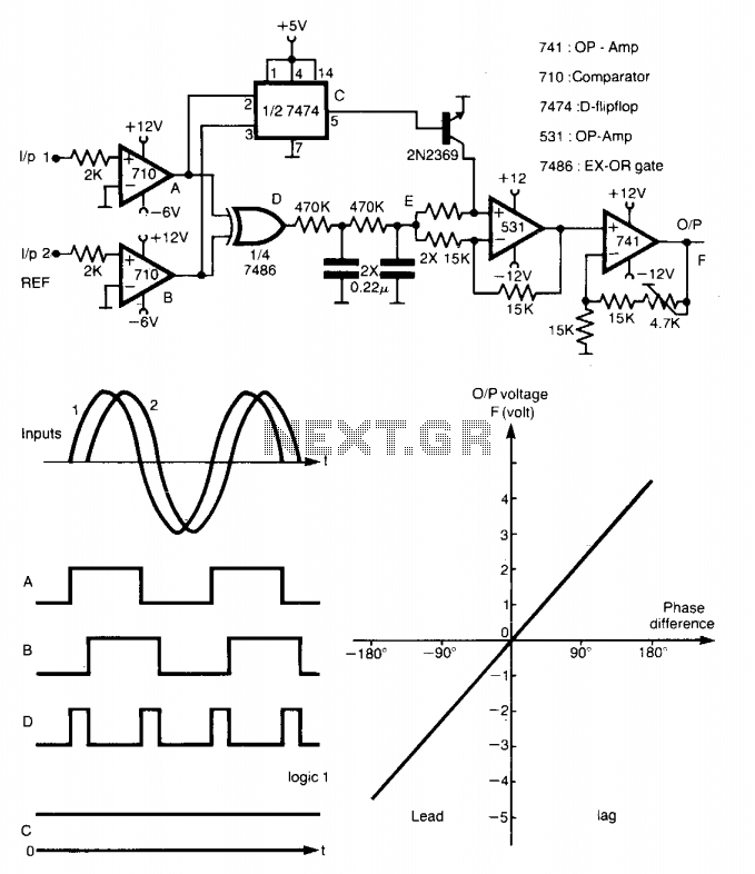
This method is capable of measuring the phase between 0 to ±180°. The generated square waves A and B are fed to a D flip-flop, which produces an output C equal to logic 1 when input A leads input...
Mercury, Oldsmobile, Plymouth, Pontiac, muscle cars, and antique classic car wiring diagrams are continuously being added to this site. The wiring diagram for the Porsche 911L engine from the 1968 model has undergone changes since the original scheme. For...
The circuit has been designed for telephone apparatus to indicate an incoming call as it rings using an LED for visual indication. BC550, an NPN general-purpose transistor, is utilized in the design. The circuit operates by detecting the ringing voltage...