
Measuring phase difference
The circuit is tested for sinusoidal inputs and indicates a linearity within 1%. Measurements are unaffected by the frequency of the inputs up to 75 kHz.
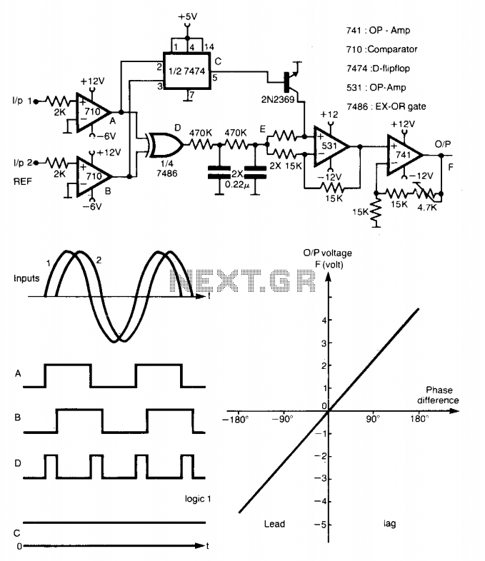
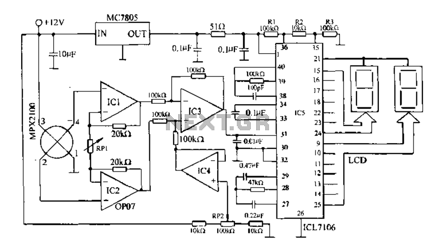
The described circuit employs a method for phase measurement that is both effective and precise. The primary components include square wave generators, a D flip-flop, an EX-OR gate, and an amplifier. The square waves, designated as A and B, are generated to represent two distinct signals whose phase relationship is to be analyzed. The D flip-flop serves as a critical element in determining the leading or lagging nature of the input signals. It outputs logic 1 when signal A leads signal B and logic 0 when the opposite occurs.
The output from the D flip-flop, labeled as C, is fed into an amplifier, which is responsible for producing a proportional output based on the phase difference between the two input signals. When C is at logic 0, indicating that input A is lagging behind input B, the amplifier's output F is positive. Conversely, when C is at logic 1, indicating that input A is leading input B, the output F becomes negative. This dual-output mechanism allows for clear differentiation between leading and lagging phases, facilitating accurate phase measurement.
The circuit has been rigorously tested with sinusoidal inputs, demonstrating a linearity of within 1%. This indicates that the circuit maintains consistent performance across a range of input conditions. Additionally, the design is robust against variations in frequency, sustaining accurate measurements for input frequencies up to 75 kHz. This capability makes the circuit suitable for various applications in electronic measurement and control systems, where precise phase information is critical.This method is capable of measuring phase between 0 to ±180°. The generated square waves A and are fed to a D flip-flop which gives an output C equal to logic 1 when input 1 leads input 2 and equal to logic 0 in case of lagging. When C = logic 0, the output of the amplifier F will be positive proportional to the average value of the output of the EX-OR.
When C = logic 1, F will be negative and also proportional to by the same factor. Hence, the output of the meter is positive in case of lagging and negative for leading. The circuit is tested for sinusoidal inputs and indicates a linearity within 1%. Measurements are unaffected by the frequency of the inputs up to 75 kHz. 🔗 External reference
Related Circuits
This circuit controls resistive and inductive loads up to 2,500W. Its main functional device is an integrated phase control circuit, the Siemens TLE3103. It includes its own power supply, a zero-voltage crossing detector circuit, and a logic driver. An...
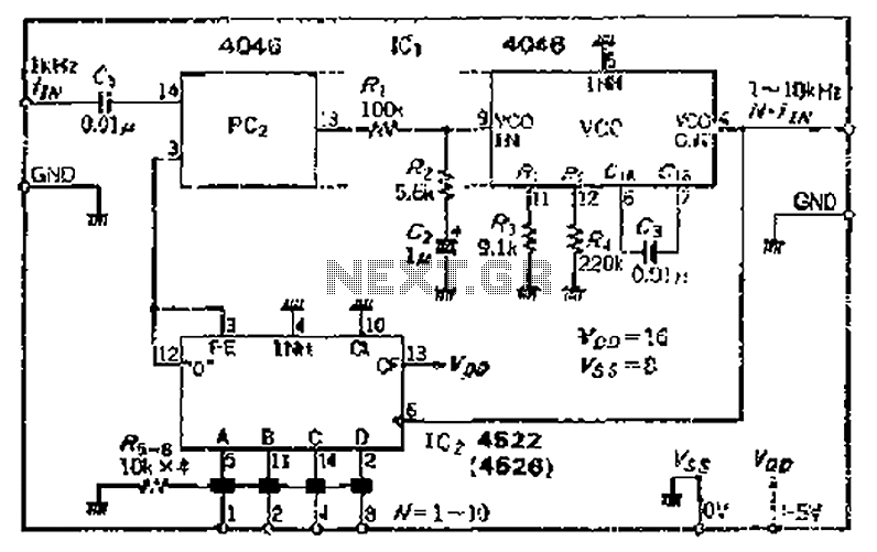
The CMOS IC 4046 Phase-Locked Loop (PLL) operates with a maximum frequency of 1 MHz. It is connected to a programmable divider, allowing it to process input frequencies. As the frequency increases by a factor of t, the circuit's...
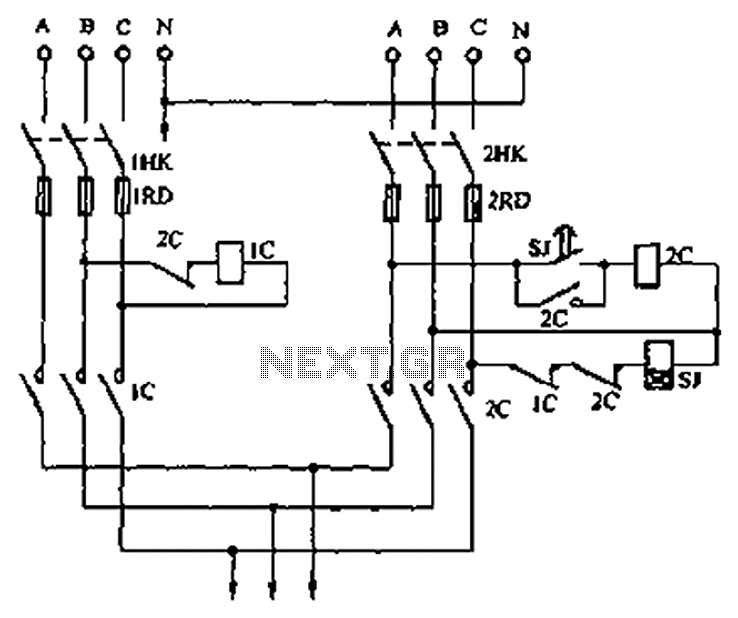
A dual three-phase power line circuit is illustrated in the figure. When the knife switches 1HK and 2HK are closed simultaneously, the normally closed contact 1C disconnects the power supply to the time relay SJ, allowing power to reach...
Digital pressure measuring circuit using AD7710/7715/7730 multifunction digital sensor signal conditioning ICs. These ICs integrate a digital interface with the control port, a clock generator, a digital filter, amplitude modulation, a programmable gain amplifier, an A/D converter, and other...

Circuit characteristics: A simple phase shift range of 180 degrees, with a practical range of 170 degrees. The circuit is influenced by temperature and is suitable for small power applications in less demanding situations. The circuit operates by utilizing a...
A 10 MHz crystal typically exhibits an impedance of 4 ohms at its series resonance and 40 kiloohms at its parallel resonance. To minimize sideband noise, the power dissipated in the crystal must be substantial; the design presented here...