
Switching Supply In Telephone Ring Generator
The telephone ring generator circuit operates through a combination of analog components that work in unison to create the required high voltage ringing signal. The core of the circuit is the switching mode power supply (SMPS), which converts low voltage DC input into the high voltage required for ringing the telephone. The CMOS Schmitt Trigger oscillator generates a square wave signal, which is crucial for the operation of the switching transistor. The 10 mH inductor plays a vital role in energy storage and transfer, allowing the circuit to produce a high voltage output when the current through it is interrupted by the switching transistor.
The choice of transistors is critical. The TIP47 and suitable PNP transistors must be selected for their high voltage ratings, ensuring that they can handle the maximum output voltage without breakdown. The configuration of the output stage, with four NPN and two PNP transistors, forms an H-bridge that effectively drives the ringing signal to the telephone. The inclusion of current limiting resistors is a preventive measure to safeguard the transistors from damage due to unexpected short circuits.
The circuit's timing is managed by the second Schmitt Trigger oscillator, which controls the duration of the ringing signal and the idle time between rings. This functionality is essential for simulating the traditional telephone ringing pattern. Adjustments to the resistors connected to pin 12 allow for customization of the ringing duration and idle time, providing flexibility in operation based on user preferences.
For applications requiring battery operation, the design accommodates this by specifying the use of six 'D' type alkaline cells, ensuring sufficient current capacity to maintain operation without performance degradation. Overall, the telephone ring generator circuit exemplifies a practical application of electronic components to achieve a specific function while allowing for user adjustments and safe operation.The telephone ring generator shown below generates the needed high voltage from a simple switching mode power supply (SMPS) which employs a CMOS Schmitt Trigger square wave oscillator, 10 mH inductor, high voltage switching transistor (TIP47 or other high voltage, 1 amp transistor) and a driver transistor (2N3053). The inductor should have a low D C resistance of 1. 5 ohms or less. The switching supply must have a load connected to prevent the voltage from rising too high, so a 22K resistor is used across the output which limits the voltage to about 120 DC with the phone ringer disconnected and about 90 volts DC connected. The output voltage can be adjusted by changing the value of the 150K resistor between pins 10 and 11 which will alter the oscillator frequency (frequency is around 800 Hz as shown).
The supply is gated on and off by a second Schmitt Trigger oscillator (pins 12/13) so that the phone rings for about 2 seconds and then the circuit idles for about a minute between rings. These times can be adjusted with the 10K and 300K resistors connected to pin 12. The push button shown is used to manually ring the phone. The 25Hz ringing frequency is generated by another Schmitt Trigger oscillator (pins 1/2) which controls the H bridge transistor output circuit.
The 6 transistors in the output stage (4 NPN, 2 PNP) should be high voltage types rated at 200 volts collector to emitter or more. The ringer will only draw around 10 mA, so the output transistors can have a low current rating but must have a high voltage rating.
I used TIP47s and small signal PNPs of unknown numbers that I had on hand, but other types such as NTE287 (NPN) and NTE288 (PNP) should work. Both have a 300 volt C-E rating and cost about $0. 95 from mail order houses. The two 470 ohm resistors connected to the output serve to limit the current in case the output is shorted.
I never tried shorting the output to see how effective the resistors are, but I did lose a couple transistors and then decided to add the resistors. They should limit the surge to around 120 mA which should be low enough to prevent damage. The circuit draws around 250 mA when the ring signal is present so if you want to operate it from batteries, six `D` type alkaline cells are recommended.
It probably won`t work with a small 9 volt battery. 🔗 External reference
Related Circuits
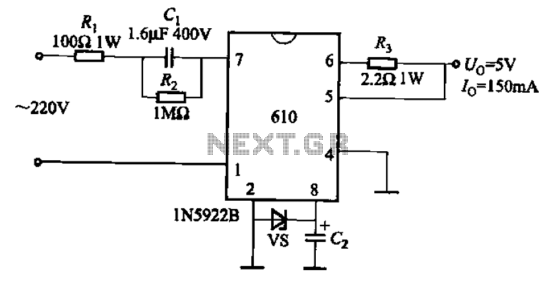
The AX610 Series has a maximum output current of 100 mA and features a scalable output current with an access regulator. The configuration includes two reverse polarity series regulators (2CW106, U: approximately 8.2V) as depicted in Figure (a). Figure...
Offline telephone tester. This circuit allows for testing a telephone instrument without the need for a telephone line. The design is straightforward. The offline telephone tester circuit is designed to evaluate the functionality of telephone instruments independently of an active...
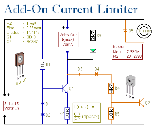
This circuit allows for setting a limit on the maximum output current from a power supply unit (PSU). It is particularly useful for initial project power-ups or during soak tests. By establishing an upper current limit, it protects both...
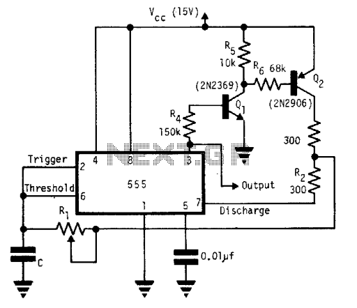
A single timing resistor ensures that the output is a square (50% duty cycle) wave at all frequency settings. Any 555 type of chip will do the job. The circuit utilizes a 555 timer IC configured in astable mode to...
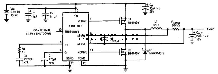
A typical LTC 1148 surface-mount application provides 5 V at 2 A from an input voltage range of 5.5 V to 13.5 V. The operating efficiency, illustrated in B, peaks at 97% and remains above 90% from 10 mA...
The electromagnetic ring launcher consists of four subcircuits: a clock circuit built around U5, a 555 oscillator/timer configured for astable operation; a countdown/display circuit built around U3, a 74190 synchronous up/down counter with BCD outputs configured for countdown operation;...