
Ripple current in a linear power supply transformer
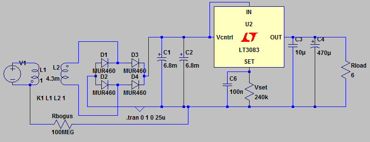
The circuit under consideration is a basic power supply design that incorporates a transformer, rectifier, voltage regulator, and filter capacitors. The transformer steps down the 230 Vrms mains voltage to a lower AC voltage suitable for rectification. The intended output voltage is 12 V DC, which necessitates careful consideration of the transformer’s specifications, particularly the secondary winding's resistance and current rating.
The transformer is expected to deliver approximately 15 Vrms, which translates to a peak voltage of about 21 V. This peak voltage is essential for ensuring that the voltage regulator can maintain a stable output voltage of 12 V under load conditions. The rectification process involves using diodes that introduce forward voltage drops, typically around 0.7 V each, resulting in a reduction of the voltage available to the regulator.
The analysis indicates a significant drop in voltage due to the series resistance of the transformer and the rectifier diodes, especially under peak load conditions. The smoothing capacitors play a crucial role in filtering the rectified output, and their ESR is a critical parameter that affects the overall performance. High ripple currents can lead to increased heating and reduced lifespan of the capacitors, making it essential to select components rated for the expected ripple current.
To address the observed current spikes, it is advisable to assess the transformer’s design, particularly its ability to handle transient loads. The transformer should be adequately rated to supply the peak currents without excessive voltage drop. A transformer with a higher current rating may be necessary if significant voltage drops are observed under load conditions.
In conclusion, the design of this power supply circuit requires careful consideration of component specifications, including transformer ratings, diode characteristics, and capacitor performance, to ensure reliable operation and minimize output ripple. Proper simulation and measurement techniques should be employed to verify performance and adjust component values as needed to achieve the desired output characteristics.BTW, I guess I should add another input cap for high frequency noise though that`s hardly relevant to this question (and the schematic is just a very rough test circuit anyhow). The goals are 0 - 12 V at up to 2 amps (1. 5 would probably be good enough, though). The voltage source is 230 $V_{rms}$ since that`s what it`ll run on, and the transfo rmer is set to simulate ~15 V RMS, so about 21 V peak. Here, the red voltage is the input to the voltage regulator, and the green/blue is current through two of the rectifier diodes. Note how the voltage is lowered a lot (from 15 Vrms - 2 diode drops) due to the series resistance combined with the 5.
5 A current peaks. This graph is at maximum output current (12 V / 6 $Omega$ load) = 1. 87 - 1. 99 A due to the output ripple; the input voltage is too low for it to regulate properly due to the drop on the secondary. What sort of series resistance would the transformer`s secondary have I`m looking at a 2x 10-15 V multi-tap transformer, with 2.
2 A per secondary rating (66 VA in total). The data sheet lists a few details, but not series resistance. Assuming a 1 $Omega$ series resistance on the secondary (as in the simulation above) and 0. 11 $Omega$ ESR on the smoothing electrolytics (some ballpark figures I found when searching), I end up with something like the above. With 0. 5 $Omega$ on the secondary, the output is great at 12 V and less (the target), but of course the 5+ amp spikes remain on the input side.
Am I in the right ballpark with 0. 5 $Omega$ on the secondary, or is twice that closer to the truth I do realize that it differs between transformers, of course, but I can`t really find any figures and I have nothing to measure myself. but in this simulation, one works and the other doesn`t. Are the current spikes of ~5-6 A for a 2 A supply normal / to be expected Same for the smoothing caps (~2.
4 A) - I assume that is the "ripple current" spec for capacitors, by the way How much does the transformer need to be rated for to handle this Surely I don`t need a 6 amp transformer to get 2 A DC out The current RMS is below 2. 2 A, but is this really okay Should I really expect such a huge voltage drop at load If the spikes are at 5 A, with 0.
5-1 $Omega$ on the secondary, I obviously lose multiple volts even before the bridge rectifier, which causes the whole thing to fail (massive output ripple). 🔗 External reference
Related Circuits
The transformer has a 240V primary and has a secondary rated 24V at 2A. The bridge rectifier contains 4 diodes, their current rating needs to be high with respect to the transformers output current; if not the current may...
In this circuit, the 7815 regulates the positive supply, and the 7915 regulates the negative supply. The transformer should have a primary rating of 240/220 volts for Europe, or 120 volts for North America. The centre-tapped secondary coil should...
This 12V power inverter circuit can be utilized to supply power to small devices that require 240 volts. It is particularly beneficial when there is a need to operate equipment designed for 240 volts. The 12V power inverter circuit is...
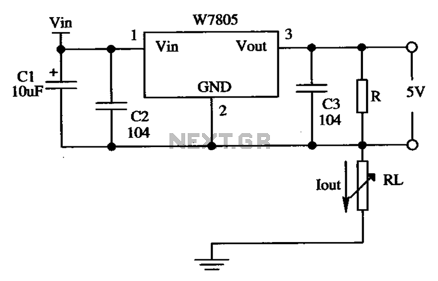
The circuit is composed of a W7805 positive current source application integration circuit that includes a voltage regulator. The W7805 regulator operates in suspension. A resistor is placed between its output terminal and the common terminal, forming a constant...
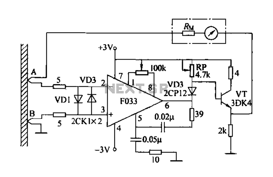
Detecting electrical equipment sometimes requires disconnecting the circuit in series for more accurate measurements of electrical current using an ammeter. However, restoring the circuit to its original state is necessary, as it can affect the normal operation of electrical...
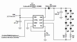
The schematic diagrams for the TPS61042 current LED driver illustrate its capability to power eight LEDs with an efficiency of 81% at 3.6V and 18.6mA. The TPS61042 is commonly utilized in applications such as white LED supply for backlight...