
Room Noise Detector
This circuit utilizes a single LED to indicate ambient noise levels at three predefined thresholds: 50 dB, 70 dB, and 85 dB. The core of the circuit comprises two operational amplifiers (op-amps) configured as a gain stage to amplify the audio signals captured by a miniature electret microphone. The electret microphone converts sound waves into electrical signals, which are then processed by the op-amps to ensure that even low-level sounds can be effectively monitored.
The circuit is designed with a switch, SW1, which has four positions. In the first position, the circuit is powered off, conserving energy. In the second, third, and fourth positions, the circuit is powered on, and the sensitivity threshold is set to 85 dB, 70 dB, and 50 dB respectively. This allows users to select the desired noise level for monitoring, making it versatile for different environments.
The LED serves as a visual indicator, flashing when the ambient noise exceeds the selected threshold. The current consumption of the circuit is notably low, drawing less than 1 mA when the LED is off, and between 12 to 15 mA when the LED is illuminated steadily. This efficiency makes the circuit suitable for prolonged use in various settings, including bedrooms where monitoring for excessive noise levels is critical for maintaining a peaceful environment.
To implement this circuit, it is recommended to place the enclosure containing the circuit in the area where noise levels are to be monitored. The design ensures that the 50 dB setting is particularly useful for quiet environments like bedrooms, allowing for effective monitoring of sound levels that could disrupt sleep. Overall, this noise level monitoring circuit is a practical solution for detecting and signaling excessive noise in various settings.One LED monitors three levels: 50, 70 & 85 dB Useful to detect too noisy environments. This circuit is intended to signal, through a flashing LED, the exceeding of a fixed threshold in room noise, chosen from three fixed levels, namely 50, 70 & 85 dB. Two Op-amps provide the necessary circuit gain for sounds picked-up by a miniature electret microphone to drive a LED.
With SW1 in the first position the circuit is off. Second, third and fourth positions power the circuit and set the input sensitivity threshold to 85, 70 & 50 dB respectively. Current drawing is <1mA with LED off and 12-15mA when the LED is steady on. * Place the small box containing the circuit in the room where you intend to measure ambient noise. * The 50 dB setting is provided to monitor the noise in the bedroom 🔗 External reference
Related Circuits
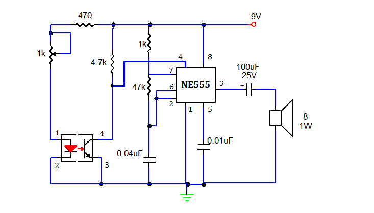
This document presents a simple smoke sensing alarm circuit utilizing a 555 timer. The circuit is designed to detect smoke and trigger an alarm when the air is contaminated. The components employed in this design include an astable multivibrator...
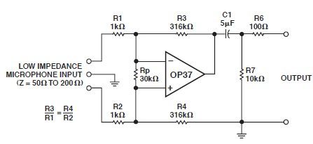
This microphone preamp schematic is an electronic circuit project utilizing the OP37 operational amplifier from Analog Devices. It functions as a fixed-gain transformerless microphone preamp, amplifying differential signals from low-impedance microphones by 50 dB, with an input impedance of...
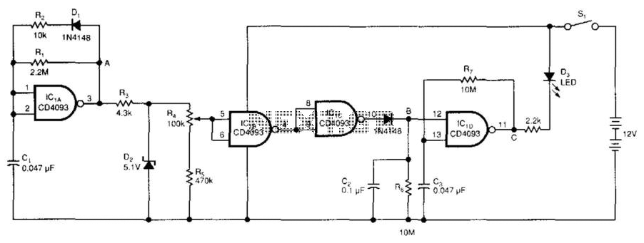
The low-voltage battery detector employs a CD4093 Schmitt trigger alongside a capacitor functioning as a 1-bit dynamic RAM. The circuit is designed to conserve power through a periodic testing method. Components IC1A, CI, R1, R2, and D1 produce a...
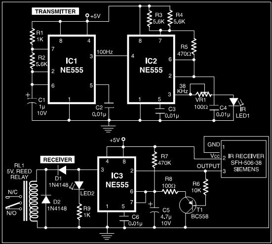
This post discusses a proximity detector circuit primarily utilizing the NE555 integrated circuit (IC). The circuit is designed for burglar alarms based on beam interruption, with the advantage that the transmitter and receiver are contained within the same enclosure,...
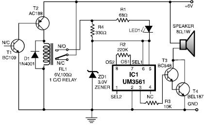
This heat detector alarm electronic project is designed using the UM3561 sound generator circuit and several common electronic components. The heat detector circuit employs a complementary pair of npn and pnp transistors to sense heat. When the temperature near...
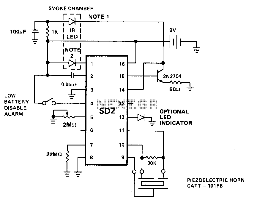
The LED predriver output pulses an external transistor, which subsequently activates the infrared light-emitting diode (IR LED) at a very low duty cycle. The desired pulse period of the IR LED is determined by the value of an external...