
Low-Battery Detector
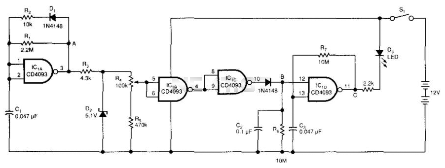
The low-voltage battery detector circuit is primarily based on the CD4093 Schmitt trigger, which is a quad 2-input NAND gate with Schmitt trigger action. This component is critical for providing a stable threshold voltage that responds to variations in the power supply. The use of a capacitor as a 1-bit dynamic RAM allows for temporary storage of the test results, which is essential in maintaining the circuit's state without continuous power consumption.
The operation begins with the periodic testing facilitated by IC1A, CI, R1, R2, and D1, which generates a narrow pulse at point A. This pulse is then processed through diodes D2, R4, and R5, which serve to regulate and divide the signal, ensuring that IC1B receives a consistent input unaffected by fluctuations in the power supply. The Schmitt trigger's threshold voltage is designed to drop in tandem with the power supply voltage, allowing for a reliable detection mechanism.
Once the threshold voltage is lower than the input voltage, IC1B transitions to a low state, triggering IC1C to output a high signal. This transition is crucial as it indicates that the battery voltage has fallen below the acceptable level. Capacitor C2, in conjunction with resistor R6, sets a time constant of 1 second, allowing the circuit to perform periodic tests every 0.1 seconds.
When the output at point A becomes high, signaling a low battery condition, IC1D, C3, and R7 generate a square waveform that activates the LED D3, providing a visual indication of the low battery status. Adjustments to the detected voltage level can be made by varying resistor R4, allowing for customization based on different battery types and voltages. Furthermore, the voltage level at D2 can be altered to test various battery voltages, enhancing the circuit's versatility and functionality in battery management applications. This design effectively combines simplicity with efficiency, making it suitable for various electronic devices requiring battery monitoring. The battery low-voltage detector uses a CD4093 Schmitt trigger and a capacitor that acts as a 1-bit dynamic RAM. The c ircuit conserves power by using a periodic test method. IC1A, CI, Rl, R2, and D1 generate a narrow, positive pulse at point A. D2, R4, and R5 regulate and divide the signal at A. Thus, the input of IC1B is independent of the power supply. Because the threshold voltage of the Schmitt trigger depends on the power supply, the threshold voltage will drop if the power-supply voltage drops. When the threshold voltage is lower than the input voltage, IC1B will become low, and IClC"s output will become high.
Capacitor C2 stores the results of the periodic test. The time constant C2 and R6 set is 1 s, and the test period is approximately 0.1 s. When point is high, which implies that the battery is low, IC1D, C3, and R7 generate a square waveform, which lights D3. You can adjust the detected voltage level by adjusting R4. You can test different battery voltages by changing the voltage level of D2. 🔗 External reference
Related Circuits
This perspective is not entirely incorrect, as the functioning of FM detectors is often considered enigmatic. The ratio detector is used to understand its operation, but without... FM detectors are critical components in communication systems, particularly in frequency modulation (FM)...
The following circuit illustrates a Water Level Detector Circuit Diagram. This circuit is based on the PIC12F683 microcontroller. Features include the ability of the PIC microcontroller to enter a sleep mode. The Water Level Detector Circuit utilizing the PIC12F683 microcontroller...
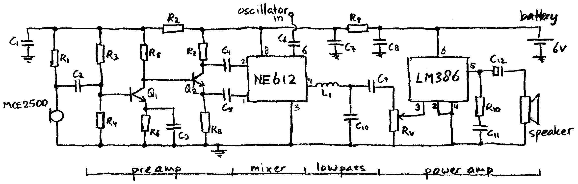
This schematic represents a simple direct-conversion heterodyne detector with a tuning range of approximately 10 kHz to 120 kHz, optimized for use with an electret microphone. The circuit operates with a low current consumption of only 8 mA, allowing...
A bright lamp flashes in synchrony with the lightning bolts, indicating the proximity and intensity of the storm. The described circuit operates as a storm warning system, utilizing a bright lamp to provide visual alerts in response to lightning activity....
The metal detector circuit consists of a probe oscillator, a PLL (phase-locked loop) circuit, and an audio alarm circuit. The probe oscillator includes a detection coil (L), transistor (V1), and several resistors (R1 to R3) and capacitors (C1 to...
This project outlines a simple water detector circuit. The components required for this project include the following: 1. One IC 555 timer, and 2. A small-sized general-purpose relay. The water detector circuit utilizes the IC 555 timer configured in a...