
Photoelectric smoke detector
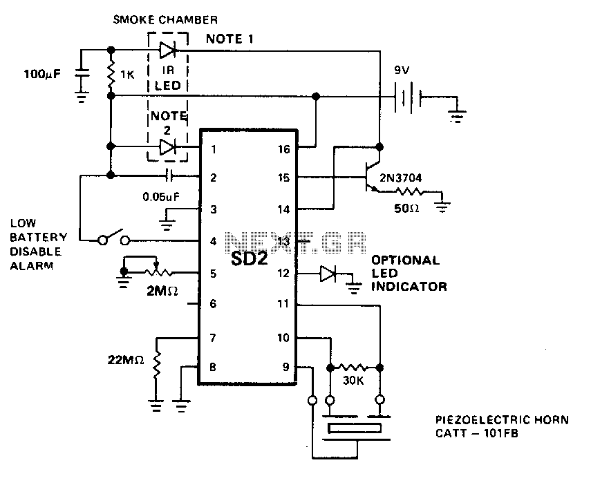
The described circuit operates as a smoke detection system utilizing a low-power infrared LED and a silicon photovoltaic cell for light sensing. The LED predriver serves as the control mechanism, producing a pulsed output that drives an external transistor. This arrangement allows the IR LED to emit light in pulses, which is critical for maintaining low power consumption while ensuring effective smoke detection.
The timing of the IR LED pulses is governed by an external timing resistor, which sets the pulse period. This allows for customization of the circuit's response time based on the specific application requirements. The trimmer resistor provides further flexibility by enabling adjustments to the pulse width, which directly affects the sensitivity of the smoke detection mechanism. By varying the pulse width, the circuit can be fine-tuned to respond to different levels of smoke density, enhancing its performance in various environments.
The light sensing element, a silicon photovoltaic cell, is critical to the operation of this circuit. By maintaining the cell at near zero bias, the design minimizes leakage currents that could otherwise lead to false positives or reduced sensitivity. This configuration allows the system to detect even the smallest changes in light intensity caused by smoke particles, with a sensitivity threshold as low as 1 mV.
Upon detecting smoke, the circuit triggers an alarm and increases the pulse repetition rate of the IR LED. This change in pulse frequency serves as an indication of smoke presence, enhancing the system's responsiveness and reliability. Overall, this smoke detection circuit combines efficient light emission, precise timing, and sensitive detection to provide an effective solution for smoke monitoring applications.The LED predriver output pulses an external transistor which in turn, switches on the infrared light emitting diode at a very low duty cycle. The desired IR LED pulse period is determined by the value of the external timing resistor. The Smoke Sensitivity is adjustable through a trimmer resistor which varies the IR LED pulse width. The light sensing element is a silicon photovoltaic cell which is held at near zero bias to minimize leakage currents
The circuit can detect signals as low as 1 mV and generate an alarm. The IR LED pulse repetition rate increases when smoke is detected. 🔗 External reference
Related Circuits

This circuit must be used between the drive voltage of such a transformer and track. On JP1, the transformer is connected to JP2, the rails are connected to JP3, is a TTL "High" position when there is a tax...
This is an infrared (IR) proximity detector circuit. A matched infrared emitter and detector pair is utilized in this circuit. The voltage-controlled oscillator (VCO) section of the LM567 tone detector integrated circuit (IC) is employed to set the emitter...
In Fig. 1 A precision DC undervoltage relay switch. The op-amp is wired as a voltage comparator, with a reference voltage applied to pin 2 and the test voltage applied to pin 3: the relay turns on when the...

The MC1596/MC1496 serves as an effective single sideband (SSB) product detector. This detector exhibits a sensitivity of 3 microvolts and a dynamic range of 90 dB while functioning at an intermediate frequency of 5 MHz. It is designed to...
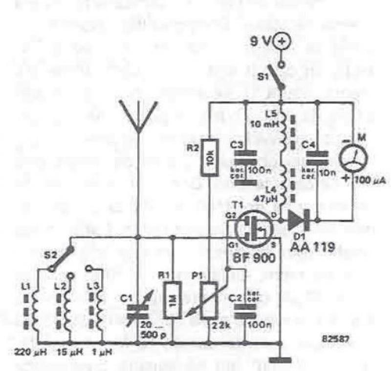
An RF field detector circuit suitable for measuring and verifying the power of antennas and transmitters can be constructed using transistors and common electronic components. This circuit employs a radio frequency transistor, specifically a MOS-FET with two gates. The...

Cellular phone detector circuit schematic using common electronic parts The cellular phone detector circuit is designed to identify the presence of a cellular phone within a specified range. This circuit utilizes basic electronic components, making it accessible for hobbyists and...