
Room Noise Detectors
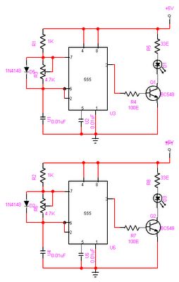
The circuit operates by utilizing a miniature electret microphone to convert sound waves into electrical signals. These signals are then fed into a pair of operational amplifiers configured for gain, allowing for the amplification of the sound levels detected by the microphone. The output from the op-amps is compared against the fixed thresholds set by the positions of switch SW1.
When the input sound level exceeds the selected threshold, the circuit activates the LED, which will flash to indicate the excessive noise level. The LED serves as a visual alert, providing immediate feedback to the user regarding the noise environment. The choice of thresholds at 50, 70, and 85 dB allows for flexibility depending on the specific needs of the user, with the 50 dB setting being particularly useful for monitoring low noise levels during sleep hours.
The operational amplifiers are configured in a non-inverting amplifier setup, providing the necessary gain to ensure that even quiet sounds can be detected and processed effectively. The design may also include additional components such as resistors and capacitors to filter noise and stabilize the circuit, ensuring reliable performance.
Overall, this circuit serves as a practical tool for monitoring ambient noise levels, particularly in environments where quiet is essential, such as bedrooms during the night.This circuit is intended to signal through a flashing LED, the exceeding of a fixed threshold in room noise, chosen from three fixed levels, namely 50, 70 & 85 dB. Two Op-amps provide the necessary circuit gain for sounds picked-up by a miniature electret microphone to drive a LED.
With SW1 in the first position the circuit is off. Second, third a nd fourth positions power the circuit and set the input sensitivity threshold to 85, 70 & 50 dB respectively. The 50 dB setting is provided to monitor the noise in the bedroom at night. If the LED is steady on, or flashes bright often, then your bedroom is inadequate and too noisy for sleep.
🔗 External reference
Related Circuits
The MFOS Noise Toaster circuit comprises seven primary components: a voltage-controlled oscillator (VCO), a white noise generator, a voltage-controlled low-pass filter, a low-frequency oscillator (LFO), a simple attack-release (AR) envelope generator, a simple voltage-controlled amplifier (VCA), and a one-watt...
The darkroom circuit is designed for one-time exposure and emits an audible signal when the developing time is reached. This circuit can be utilized for photofinishing large timers and other applications. It comprises components such as FET VTi, resistors,...
The objective of this project is to create a controller-based model that counts the number of individuals entering a specific room and activates the lighting accordingly. This is achieved through the use of sensors that detect the current number...
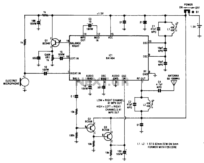
The circuit utilizes Q1 to buffer the right-channel balance output, while Q2 and Q3 create a VOX circuit. When the microphone signal level increases, the VOX output also rises, causing the multiplexer within IC1 to route the high-gain left-channel...
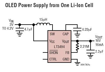
The LT3494 and LT3494A are low-noise boost converters that integrate a power switch, Schottky diode, and output disconnect circuitry. These devices utilize an innovative control technique that results in minimal output voltage ripple and high efficiency across a broad...
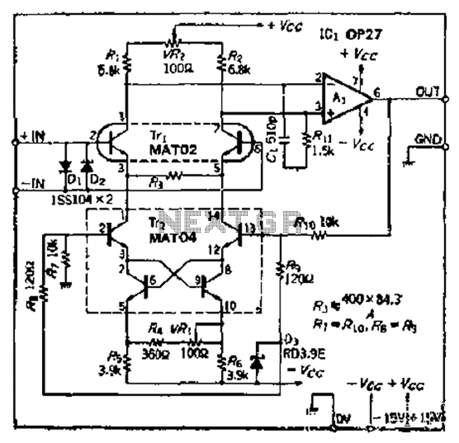
The Bong ordinary differential amplifier circuit differs from a standard differential circuit by incorporating a voltage-current conversion circuit, which consists of resistors R and Rl. The operational amplifier (OP amp) includes a voltage divider that subsequently converts the voltage...