
Rotation Sensor Circuit Using 555 PCB

The rotation sensor circuit utilizes a 555 timer in monostable or astable mode, depending on the desired functionality. In monostable mode, the circuit generates a single output pulse when triggered by the rotation. This pulse can be used to activate a relay or transistor, which in turn powers the connected device, such as a motor or buzzer. The duration of the output pulse is determined by the resistor and capacitor values connected to the 555 timer.
In astable mode, the circuit continuously oscillates, producing a square wave output that can be used to drive the connected device in a more dynamic manner. The frequency of this oscillation is also determined by the resistor and capacitor values, allowing for customization based on the application's requirements.
The rotation sensor may incorporate additional components, such as potentiometers for adjusting sensitivity or diodes for protecting against reverse polarity. Proper placement of the rotation sensor and careful calibration of the timing components are crucial for ensuring reliable operation. The circuit can be powered by a standard DC supply, and the output can easily interface with various devices, making it suitable for a wide range of applications in automation and control systems.Circuit The picture shows the circuit diagram of a rotation sensor that can turn on a device like motor or buzzer while the circuit assembly rotates. The circuit is based on basic 555 timer operation. 🔗 External reference
Related Circuits
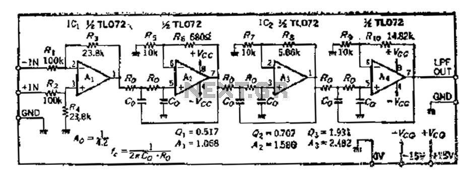
A 36 dB/octave Butterworth filter consists of three sub-structures, each stage containing two filter sections. The design aims to achieve specific 3 dB frequency characteristics. The filter needs to be normalized to a value of 0 across all levels,...
A robot can be defined as an electro-mechanical system with the capability of sensing its environment, manipulating it, and acting according to a preprogrammed sequence. It is a machine that... Robots are complex systems that integrate various components to perform tasks...
What exactly is a multivibrator? I suppose one definition would be 'a circuit which has several states'. This will do for now, it's quite loose so leaves plenty to the imagination! Conventional multivibrators have only two stages and come...
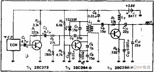
The circuit functions as a frequency modulation (FM) transmitter that operates within the 76 to 90 MHz FM radio band, commonly referred to as a wireless microphone. It receives signals through an FM radio receiver. The circuit is capable...
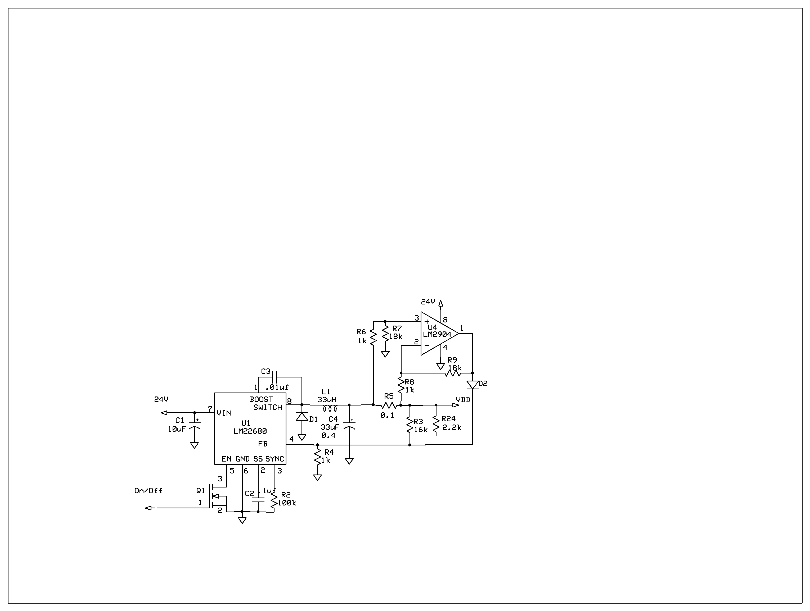
The product requires a voltage-controlled, current-limited power supply. Various switcher chips have been used with an op-amp to provide feedback for a current sense voltage to the feedback pin. Currently, an LM22680 is in use, but it has shown...
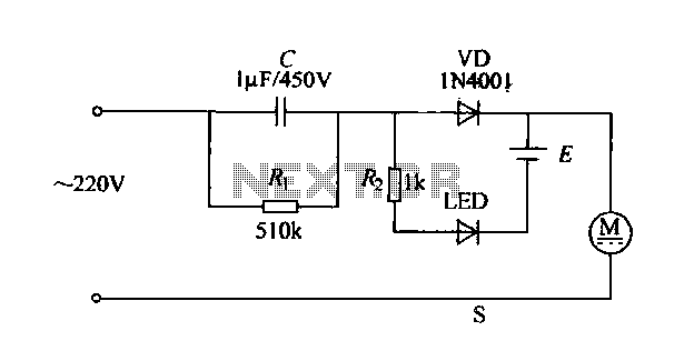
The electric shaver circuit is illustrated in Figure 1-17. It features a buck capacitor (C) rated at 1 µF and 450V, which connects through diode VD to charge 1.2V nickel-cadmium batteries. Additionally, after the buck converter, there is a...