
Astable multivibrator circuits
As Tr2 starts to turn on, Tr2's collector will start to fall and will pull down the right hand end of C2. Since C2 is a capacitor, the voltage across it cannot suddenly change so the left hand end of C2 will also start to fall. This will rob current from Tr1 which will start to turn off and its collector voltage will start to rise. As it does so, C1 will feed this rising voltage into Tr2's base, helping it to turn on - so the circuit will 'collapse' into a state where Tr2 is fully on and Tr1 is fully off.
As Tr2 quickly switches from off to on, its collector falls from Vcc to 0v and (by capacitor action) the base of Tr1 will be reversed biased from about 0.6v to (Vcc-0.6v) below earth as the left end of C2 follows the right end downwards.
Now R3 starts to charge C2's left end positively from near -Vcc (below the 0v line) towards 0v and past 0v towards Vcc. Remember that Tr2 is turned on, so the right end of C2 is clamped to 0v (via Tr2).
As the left hand end of C2 gets to around +0.6v, Tr1 starts to conduct and the sequence repeats.
So the circuit switches between two states, Tr1 on (Tr2 off) and Tr2 on (Tr1 off). The time in each state is determined by R1C1 and R3C2 and is 0.69CR (but read on). So the circuit gives a 50:50 mark space and is a 'fairly' reliable and predictable oscillator. The values shown will give a frequency around 1kHz (0.5 mSec on, 0.5mS off).
I say 'fairly' reliable because there are a couple of points... Imagine that Tr1 and Tr2 are both conducting and both capacitors are 'discharged': R1's current flows into Tr2 and R3's current flows into Tr1. The capacitors are 'discharged' so no current is flowing in them: the circuit is in a stable state and is not oscillating. This condition happens and is probably the biggest single problem with the common multivibrator - and with several of its relatives.
The 'astable multivibrator' (to give this circuit its 'proper' name was invented in the days of valves and was common with early germanium transistors. These has a gain of maybe 20 (gain is the ratio of collector current to base current: feed 1 microamp into the base of a transistor and, with a gain of 20, you will get 20 microamps collector current). With these typically R2 and R4 might be 1K, R1 and R3 10K. Then silicon transistors came out: these had higher gains. This 'failure to oscillate' became common: silicons had more gain and the circuit oscillates more reliably if the transistors are not turned too hard on: I've chosen R1:R2 of 100, which would suit a transistor having a gain of at least 100.
Nevertheless: I would not use such a simple multivib in a critical part of a commercial circuit today, because it can fail to start. But it remains an interesting circuit and a good learning exercise! An obvious fact: for all transistor circuits there exists a complement, replace all PNP transistors by NPN and vice versa, reverse all diodes and other 2 terminal polarised components. An identical but complementary circuit results. This is one of the nice things you can do with transistors - but not with ICs. Virtually all ICs have a negative earth and do not work in a complementary version. The reasons for this are mainly historical - the early silicon transistor fabrication made better NPN transistors than PNP. Although modern fabrication makes both, there are very small intrinsic performance differences (due to differences in electron and hole flow) and NPN is therefore the more common model. As I have said, the period of the multivib is 0.69CR. But this only applies for low voltages. When one transistor turns on, the base of the other transistor gets pulled very hard negative (well below the 0v line) and the base is turned off. But transistor base junctions cannot stand a lot of reverse voltage: modern ones seem to be around 10v. If you try and put a larger reverse voltage on the base - the transistor base emitter junction conducts like a zener diode. This interferes with the formula - and you get a shorter time than you expect.
The astable multivibrator is a fundamental circuit used in various applications, including clock generation, tone generation, and pulse-width modulation. It consists of two transistors (Tr1 and Tr2), two capacitors (C1 and C2), and resistors (R1, R2, R3, and R4). In its astable configuration, the circuit continuously oscillates between two states, producing a square wave output. The timing of the oscillation is determined by the RC time constants associated with the capacitors and resistors in the circuit.
When Tr1 is turned on, it allows current to flow through R3 into its base, causing it to conduct. This, in turn, starts charging capacitor C1. Once the voltage across C1 reaches a threshold, it turns on Tr2, which then pulls down the voltage across C2, causing Tr1 to turn off. The process then repeats, creating a feedback loop that sustains oscillation.
The frequency of oscillation can be calculated using the formula f = 1/(T1 + T2), where T1 and T2 are the time periods for each state. The values of the resistors and capacitors can be selected to achieve the desired frequency. For reliable operation, it is essential to ensure that the transistors are not driven into saturation, as this can lead to failure in oscillation. Additionally, the circuit's performance may be affected by the characteristics of the transistors, especially in terms of gain and reverse voltage tolerance.What exactly is a multivibrator? I suppose one definition would be 'a circuit which has several states'. This will do for now, it's quite loose so leaves plenty to the imagination! Conventional multivibrators have only two stages and come in three flavours: astable (where neither state is stable and the circuit oscillates between the two states); monostable (where one state is stable, the other transient). And bistable, where the circuit can be flipped from state one to state two. The fact that it can be 'flopped' back again leads to another term 'flip-flop' - but you can call an astable an astable flip-flop!
Then you can get tristables - and one circuit I shall introduce is a 'donkey simulator' where 3 transistors are combined to make 3 separate astable mulivibrators! Assume that the Tr1 is turned hard on (if you've indexed this site by 'hard on' sorry - it's not for you!) and Tr2 is not conducting, so the right end of C2 is at Vcc: current is flowing into the base of Tr1 via R3 causing it to conduct, so the left end of C1 is at 0v. Assume C1 is not charged: its left end is clamped to 0v by Tr1 but its right end is being fed from Vcc via R1, so it will start to charge up through R1, its right end moving positive towards Vcc.
At a certain point there will be enough voltage on the right end of C1 to cause Tr2 to start conducting. As Tr2 starts to turn on, Tr2's collector will start to fall and will pull down the right hand end of C2.
Since C2 is a capacitor, the voltage across it cannot suddenly change so the left hand end of C2 will also start to fall. This will rob current from Tr1 which will start to turn off and its collector voltage will start to rise.
As it does so, C1 will feed this rising voltage into Tr2's base, helping it to turn on - so the circuit will 'collapse' into a state where Tr2 is fully on and Tr1 is fully off. As Tr2 quickly switches from off to on, its collector falls from Vcc to 0v and (by capacitor action) the base of Tr1 will be reversed biased from about 0.6v to (Vcc-0.6v) below earth as the left end of C2 follows the right end downwards.
Now R3 starts to charge C2's left end positively from near -Vcc (below the 0v line) towards 0v and past 0v towards Vcc. Remember that Tr2 is turned on, so the right end of C2 is clamped to 0v (via Tr2). As the left hand end of C2 gets to around +0.6v, Tr1 starts to conduct and the sequence repeats. So the circuit switches between two states, Tr1 on (Tr2 off) and Tr2 on (Tr1 off). The time in each state is determined by R1C1 and R3C2 and is 0.69CR (but read on). So the circuit gives a 50:50 mark space and is a 'fairly' reliable and predictable oscillator. The values shown will give a frequency around 1kHz (0.5 mSec on, 0.5mS off). I say 'fairly' reliable because there are a couple of points... Imagine that Tr1 and Tr2 are both conducting and both capacitors are 'discharged': R1's current flows into Tr2 and R3's current flows into Tr1.
The capacitors are 'discharged' so no current is flowing in them: the circuit is in a stable state and is not oscillating. This condition happens and is probably the biggest single problem with the common multivibrator - and with several of its relatives.
The 'astable multivibrator' (to give this circuit its 'proper' name was invented in the days of valves and was common with early germanium transistors. These has a gain of maybe 20 (gain is the ratio of collector current to base current: feed 1 microamp into the base of a transistor and, with a gain of 20, you will get 20 microamps collector current).
With these typically R2 and R4 might be 1K, R1 and R3 10K. Then silicon transistors came out: these had higher gains. This 'failure to oscillate' became common: silicons had more gain and the circuit oscillates more reliably if the transistors are not turned too hard on: I've chosen R1:R2 of 100, which would suit a transistor having a gain of at least 100. Nevertheless: I would not use such a simple multivib in a critical part of a commercial circuit today, because it can fail to start.
But it remains an interesting circuit and a good learning exercise! An obvious fact: for all transistor circuits there exists a complement, replace all PNP transistors by NPN and vice versa, reverse all diodes and other 2 terminal polarised components. An identical but complementary circuit results. This is one of the nice things you can do with transistors - but not with ICs. Virtually all ICs have a negative earth and do not work in a complementary version. The reasons for this are mainly historical - the early silicon transistor fabrication made better NPN transistors than PNP.
Although modern fabrication makes both, there are very small intrinsic performance differences (due to differences in electron and hole flow) and NPN is therefore the more common model. As I have said, the period of the multivib is 0.69CR. But this only applies for low voltages. When one transistor turns on, the base of the other transistor gets pulled very hard negative (well below the 0v line) and the base is turned off.
But transistor base junctions cannot stand a lot of reverse voltage: modern ones seem to be around 10v. If you try and put a larger reverse voltage on the base - the transistor base emitter junction conducts like a zener diode.
This interferes with the formula - and you get a shorter time than you expect. 🔗 External reference
Related Circuits
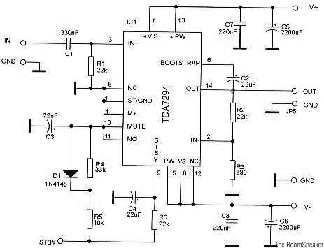
The TDA7294 is a monolithic integrated circuit housed in a Multiwatt15 package, designed to deliver high output power of up to 100W. It is intended for use as an audio Class AB amplifier in high-fidelity applications. The TDA7294 is a...

For the time it takes to charge to 0.6V, the other capacitor has already charged significantly (a value that cannot be determined because the setup does not function until one of the two states—Q1 is on or Q2 is...
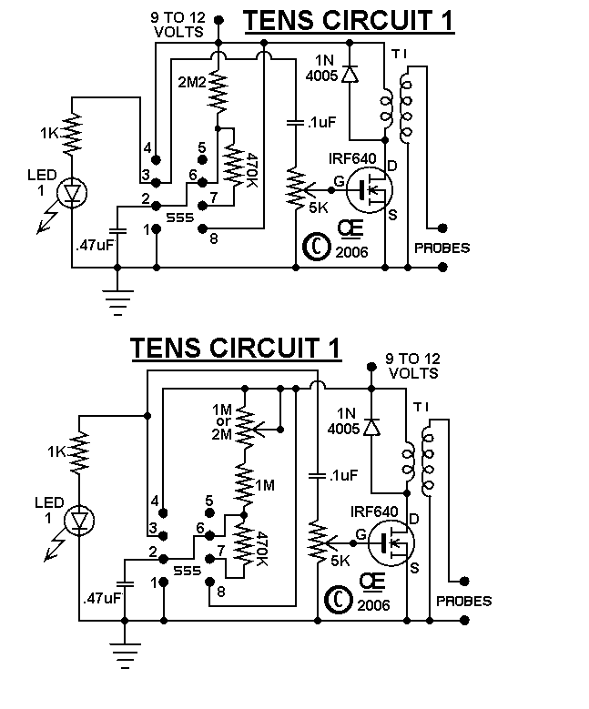
The circuits were originally designed for an individual with muscle issues. Although they were reported to function effectively, the use of these devices is not recommended for anyone, and no responsibility or liability is accepted for their assembly or...
The circuits in Figure 1 and Figure 2 demonstrate specific advantages over the circuit presented in the Design Idea in EDN, titled "Circuit detects first event," published on May 3, 2001, page 89. The n-player first-event detection circuit provides...
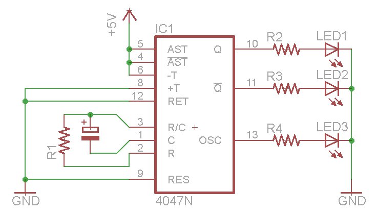
The oscillator output generates a signal that is approximately twice the frequency of Q. The other pins will be considered subsequently. In a brief video demonstration, LEDs are connected to all three outputs, illustrating the alternating behavior of Q...
The monostable 555 timer multivibrator circuit, also known as a one-shot monostable multivibrator, functions as a retriggerable pulse generator. The term "monostable" indicates that the circuit has only one stable state, with the unstable state referred to as the...